
4.3 Connect External Relay
Wiring a PiBot IsoSwitch V4
The PiBot IsoSwitch V4 gives three relay channels, each with an NC / COM / NO changeover contact and an optocoupler input stage. It runs from its own 4.5–40 V DC supply (24 V by default) and takes three logic signals on S1 S2 S3. V4.7B offers two 5 V signal routes. The C connector is recommended when the C axis is unused because it avoids the shared spindle, laser, MOSFET, RS485 and 0–10 V signals.
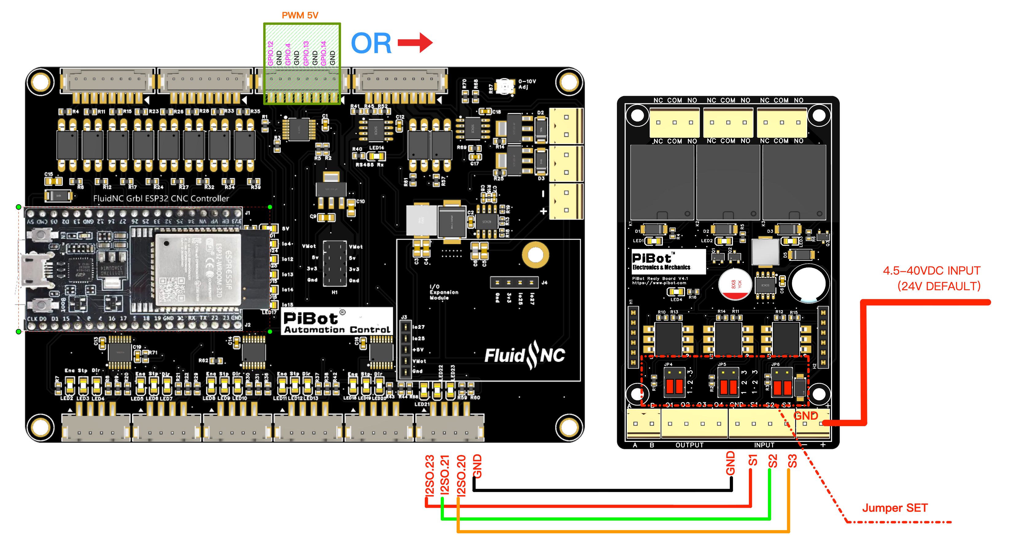
Which outputs you can use on V4.7B
| Route | Pins | Level | Notes |
|---|---|---|---|
| I2SO output — recommended when C is unused | I2SO.23 I2SO.21 I2SO.20 + GND | 5 V signal | The C connector in the test YAML. Using it for relays makes that motor connector unavailable. |
| 5 V buffered signal header | GPIO.12 GPIO.4 GPIO.13 GPIO.14 + GND | 5 V signal | Every pin here already has another job; this header supplies control signals, not relay-coil power. |
GPIO.4 is spindle PWM (tool 0) and drives a MOSFET channel; GPIO.12 is laser (tool 1) and drives the other MOSFET channel; GPIO.13 is the 0–10 V generator; GPIO.14 is the RS485 direction line and 0–10 V Reverse. Taking one for a relay removes that function.Trigger jumpers on the relay board
Each relay has its own jumper block — JP4→S1, JP5→S2, JP6→S3. The silkscreen numbers the rows 1 (bottom), 2 (middle), 3 (top); each column takes one jumper, down bridging 1–2 and up bridging 2–3.
| Setting | Left column | Right column | Effect |
|---|---|---|---|
| Active High — default | down (1–2) | down (1–2) | A high signal energises the relay. |
| Active Low | up (2–3) | up (2–3) | A low signal energises the relay. |
| Always on | up (2–3) | down (1–2) | Stays energised, input ignored. |
| Always off | down (1–2) | up (2–3) | Stays de-energised, input ignored. |
Wire and prove the control side first
- Disconnect the V4.7B and relay-board supplies.
- Confirm the C connector is unused, or choose one compatible pin from the 5 V signal header and update the YAML accordingly.
- Wire I2SO.23/21/20 and GND to S1/S2/S3/GND, then power the relay board from its own supply.
- Set JP4/JP5/JP6 and load the YAML mapping below.
- With no load attached, send one command at a time and check the click and LED.
- Measure COM–NO and COM–NC continuity before connecting the real load.
YAML and test commands
Matching the drawing, where I2SO.23→S1, I2SO.21→S2 and I2SO.20→S3. Substitute your own pins if you wired a different output.
coolant:
  mist_pin: I2SO.23        # S1 - M7 on, M9 off
  flood_pin: I2SO.21       # S2 - M8 on, M9 off
  delay_ms: 0

user_outputs:
  digital0_pin: I2SO.20    # S3 - M64 P0 on, M65 P0 off
Pass: each command changes only its assigned relay and the continuity reading agrees with the selected contact. Fail: a relay starts unsafe, more than one changes, or a command does not release it — disconnect both supplies and correct the YAML, jumpers or contact wiring before adding a load.
io.12-MOS-GND and io.4-MOS-GND. Use one only when the coil voltage matches Vmot-main and its steady-state and inrush current are within the channel limit. This is a different wiring method from the logic-input PiBot IsoSwitch V4 above; never connect a coil to the 5 V signal header.