
PiBot IsoSwitch V4
The relay board
The PiBot IsoSwitch V4 carries three independent relays. Each gives you a dry changeover contact — NC, COM and NO. The input stage uses optocouplers, while the relay contacts keep the switched circuit physically separate from the controller-side signal wiring. That separation does not replace correct enclosure, fusing, spacing or load ratings.
Two quite different jobs are worth knowing about. The obvious one is switching a load. The other is using a contact as an enable signal: some servo drives will not run until an external contact is closed, and wiring that enable input through one of these relays lets G-code arm and disarm the drive.
The Always on and Always off jumper positions act as a manual override for bench checks, so the contact wiring can be proved before a controller signal is connected.
| Terminal group | Pins | What it is |
|---|---|---|
| Power in | − + | 4.5–40 V DC, 24 V by default. This powers the relay coils — it does not come from the controller. |
| INPUT | GND S1 S2 S3 | The three trigger signals, one per relay, plus the shared return. Accepts 5 V or 3.3 V logic from the mainboard. |
| Contacts | NC COM NO ×3 | The switched side. NO is open until the relay is energised; NC is closed until it is. |
| OUTPUT | O1…O4 GND | Marked (future) on the silkscreen — reserved, not used by this procedure. |
Trigger jumpers — JP4 / JP5 / JP6
Each relay has its own two-jumper block: JP4 → S1, JP5 → S2, JP6 → S3. The block decides what the signal on that input means. The silkscreen numbers the three rows 1 (bottom), 2 (middle) and 3 (top), and each column takes one jumper — down bridges 1–2, up bridges 2–3.
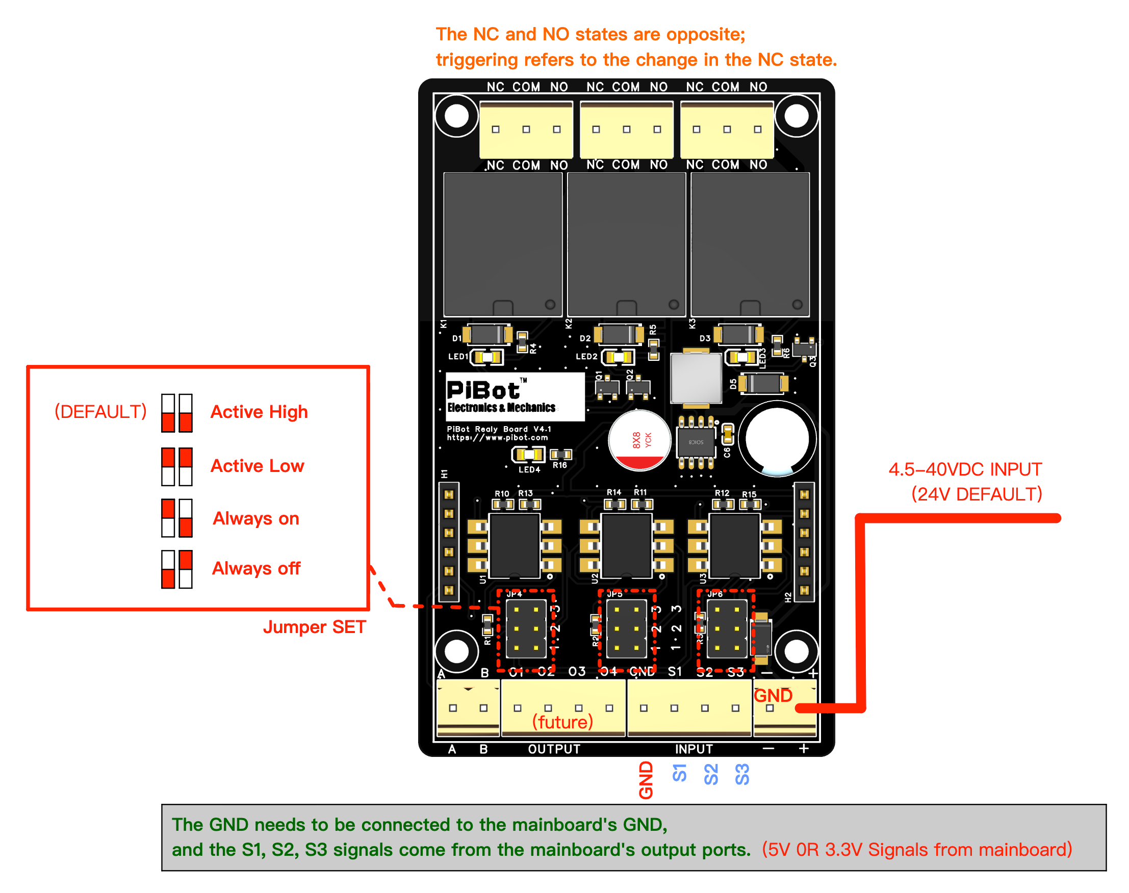
| Setting | Jumpers | Left column | Right column | What the relay does |
|---|---|---|---|---|
| Active High — default | down (1–2) | down (1–2) | A high signal on that input energises the relay. | |
| Active Low | up (2–3) | up (2–3) | A low signal energises the relay — the inverse of the above. | |
| Always on | up (2–3) | down (1–2) | Relay stays energised, ignoring the input. | |
| Always off | down (1–2) | up (2–3) | Relay stays de-energised, ignoring the input. |
Choose the jumper polarity and the physical NO or NC terminal together. Decide what the machine must do while booting, after reset or alarm, and when either supply is removed; then confirm every state with a continuity meter before connecting the load.
Controller compatibility
The four documented controllers use the same relay board but expose different signal sources. Each controller has its own wiring drawing and pin notes on its 4.3 page — use the links in the last column.
| Controller | 5 V buffered output header | I2SO output | Extra GPIO (3.3 V) | Its 4.3 page |
|---|---|---|---|---|
| V5.88 Ultra | GPIO.4 GPIO.5 GPIO.45 GPIO.46 | I2SO.23 I2SO.21 I2SO.20 | yes — GPIO.3 GPIO.10 GPIO.15 | V5.88 4.3 |
| V4.96 Pro | GPIO.4 GPIO.12 GPIO.14 GPIO.13 | I2SO.23 I2SO.21 I2SO.20 | — | V4.96 4.3 |
| V5.77 Carrier | GPIO.4 GPIO.5 GPIO.45 GPIO.46 | I2SO.23 I2SO.21 I2SO.20 | — | V5.77 4.3 |
| V4.7B | GPIO.12 GPIO.4 GPIO.13 GPIO.14 | I2SO.23 I2SO.21 I2SO.20 | — | V4.7B 4.3 |
Wiring drawings by controller
Choose the drawing for your controller. The orange boxes in each drawing are alternative signal sources; use one route, not all of them. Open the matching 4.3 page for its jumper, shared-pin and YAML notes.
V5.88 Ultra — three signal routes
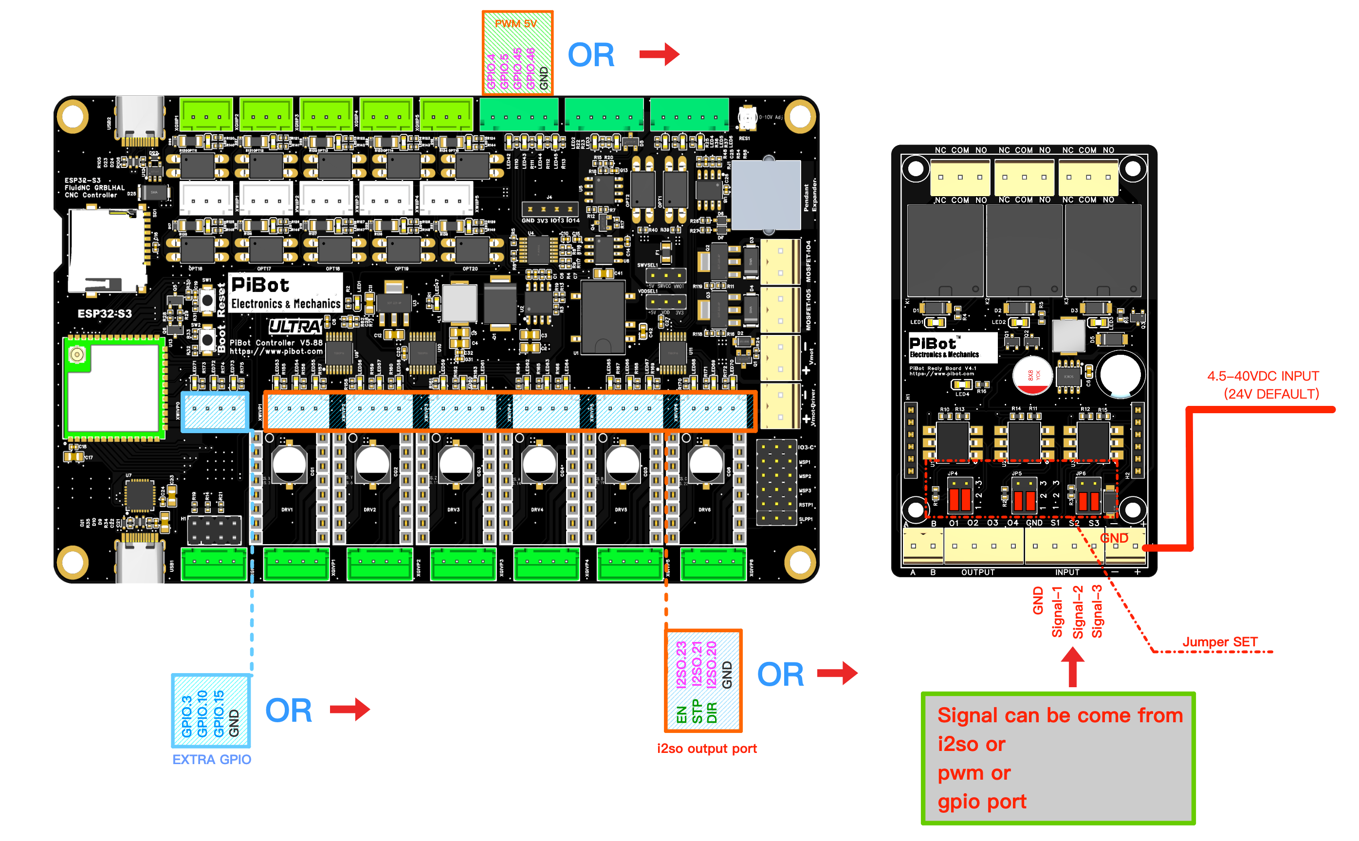
5 V buffered outputs, unused-axis I2SO, or 3.3 V Extra GPIO. Open V5.88 instructions →
V4.96 Pro — two signal routes
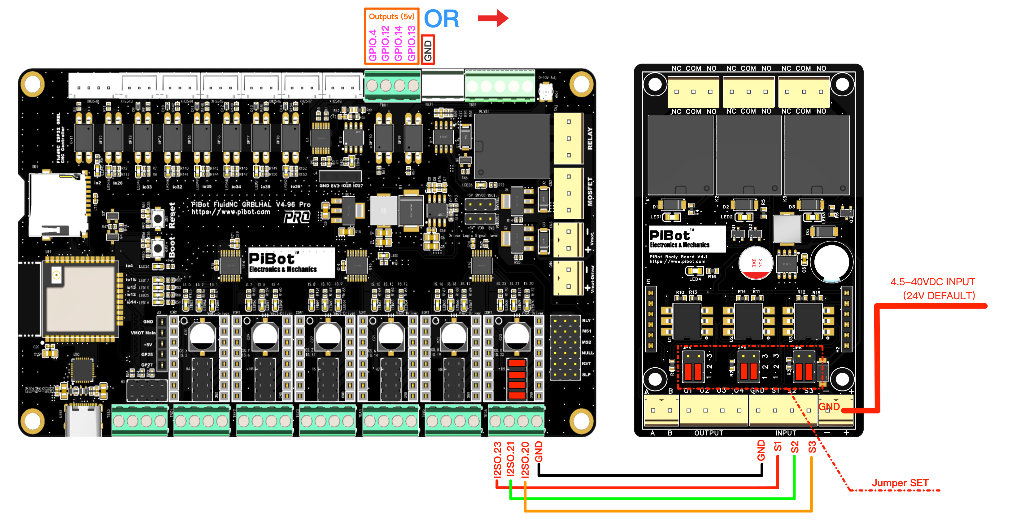
5 V buffered outputs or an unused motor slot’s I2SO terminals. Open V4.96 instructions →
V5.77 Carrier — two signal routes
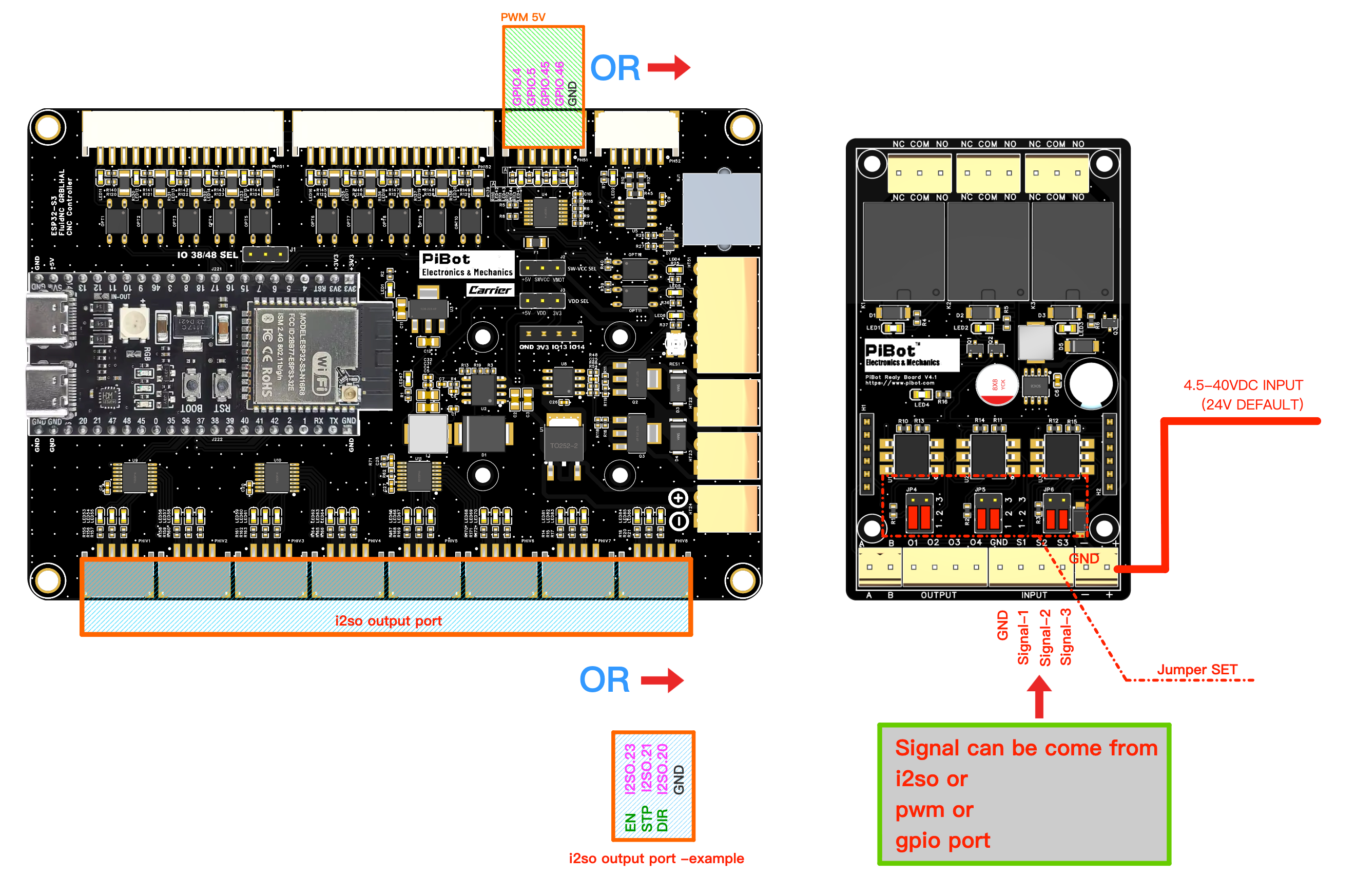
5 V buffered outputs or an unused PH2.0 I2SO axis connector. Open V5.77 instructions →
V4.7B — two signal routes
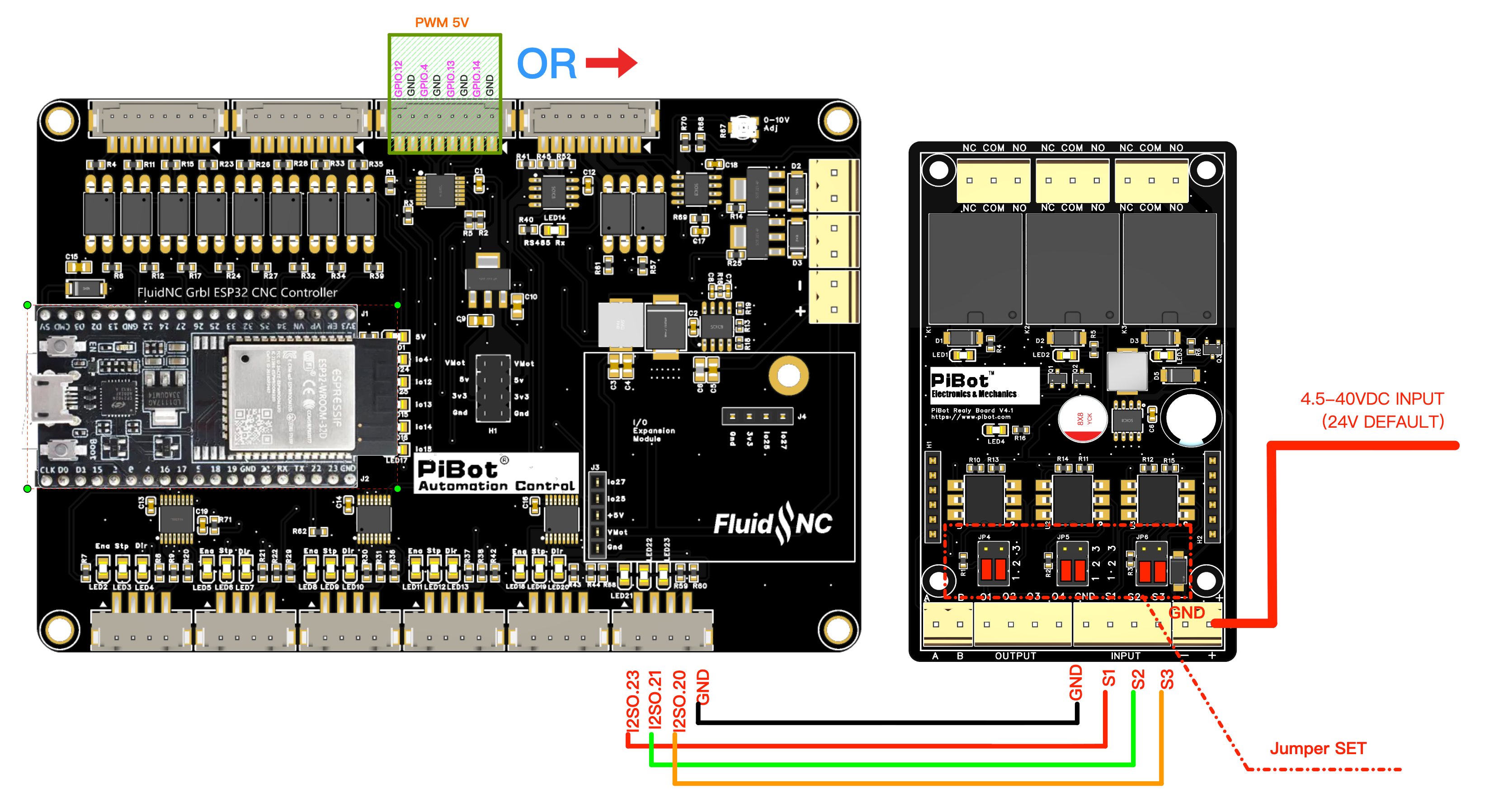
The unused C-axis I2SO connector is preferred; 5 V signals are shared. Open V4.7B instructions →
Wiring and first test
- Everything off. Controller and relay-board supply both disconnected; LEDs out.
- Set the jumpers on JP4/JP5/JP6 for the behaviour you want. Leave them at the default Active High unless you have a reason not to.
- Wire three signals and a ground from one of your board’s outputs to S1 S2 S3 and GND. Use fewer than three if you only need one or two relays — the unused inputs simply stay unconnected.
- Power the relay board from its own 4.5–40 V DC supply on the − / + terminals. 24 V is the default.
- Declare the pins in your YAML — see below — and reload the configuration.
- Test with no load connected. Send one command at a time and confirm only the intended relay clicks and its LED changes.
- Check the contact with a meter before wiring the real load, so you know NO and NC are where you expect in the resting state.
- Only then wire the load through the contacts, on the far side of the relay, with its own protection.
YAML — a worked example
This worked I2SO example uses I2SO.23 → S1, I2SO.21 → S2 and I2SO.20 → S3, matching all four board-specific drawings. Coolant gives two relays the simple M7/M8/M9 commands; a user output gives the third.
coolant:
  mist_pin: I2SO.23        # S1 - M7 on, M9 off
  flood_pin: I2SO.21       # S2 - M8 on, M9 off
  delay_ms: 0

user_outputs:
  digital0_pin: I2SO.20    # S3 - M64 P0 on, M65 P0 off
| Relay | Input | Signal in this example | Turn on | Turn off |
|---|---|---|---|---|
| K1 | S1 | I2SO.23 — mist | M7 | M9 |
| K2 | S2 | I2SO.21 — flood | M8 | M9 |
| K3 | S3 | I2SO.20 — user output 0 | M64 P0 | M65 P0 |
mist_pin: gpio.4.M9 releases K1/K2 in this example, and M65 P0 releases K3. The measured COM–NO / COM–NC state matches the selected jumper polarity.Quick troubleshooting
- Nothing clicks at all. The relay board has no supply of its own, or the INPUT GND is not tied to the mainboard GND. Both are required.
- A relay is on the moment power is applied and never turns off. Its jumper block is on Always on, or on Active Low while the output rests low.
- A relay never turns on. Its jumper block is on Always off, or on the wrong one of Active High / Active Low for that output’s resting level.
- The load is on when the machine is idle. You are on the NC contact when you wanted NO, or the trigger polarity is inverted. Decide the safe state first, then pick the contact and the jumper to match.
- The command does nothing. The pin is not declared in the YAML, or it is declared on a pin you did not wire. On V4.96 Pro, the I2SO route also needs the slot routing jumpers installed.
- V4.96 Pro: the axis stopped working, or something got damaged. A slot must never have both the routing jumpers installed and an on-board driver fitted.
- The spindle, laser or 0–10 V output stopped working after wiring a relay. You took a pin that shares that function — especially likely on V4.7B. Move the relay to an I2SO output instead.