
PiBot STM32 I/O Expander V5 Complete Manual
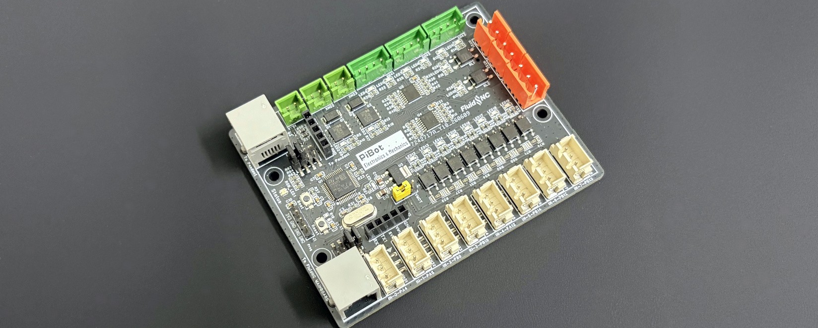
A detailed installation and configuration guide for adding 18 numbered I/O channels to a compatible FluidNC controller, with a downstream RJ12 path for a PiBot pendant.

 1. Product overview and package contents
 What V5 adds
- Eight optocoupler inputs instead of the mixed V4 input arrangement.
- Six buffered 5 V digital/PWM outputs, two more than V4.
- Two onboard normally-open PhotoMOS relay outputs with indicator LEDs.
- Two External-V MOSFET outputs for low-voltage DC loads.
- Independent RX/TX swap jumpers on both the mainboard and pendant sides.
- Dedicated RJ12 sockets for the controller and downstream pendant.
Included in every package
- Expander V5 main unit × 1
- Adapter for PiBot 4.x controller × 1
- RJ12 communication cable × 1
The 4.x adapter is used with V4.96 Pro and V4.7B. V5.88 Ultra and V5.77 Carrier use the documented direct RJ12 connection.
 2. Before installation
 Prepare
- Compatible PiBot FluidNC controller
- Supplied RJ12 cable and 4.x adapter when required
- Small insulated screwdriver
- Computer with FluidNC WebUI or FluidTerm
- Multimeter for wiring checks
 Disconnect first
- Spindle and laser enable circuits
- Pumps, valves, solenoids and relay coils
- Every load on #8–#17
- External V supply
- Pendant battery and machine power
Confirm first
- Controller model and revision
- Active YAML filename
- Correct UART GPIO pair
- 5 V or 12/24 V sensor supply
- Load voltage, current and safe off-state

 3. PinMap and board callouts 1–11
Open the high-resolution PinMap and follow the numbered explanation below. FluidNC uses the blue/orange I/O numbers printed on this drawing; it does not use STM32 names such as PA4 or PB11.
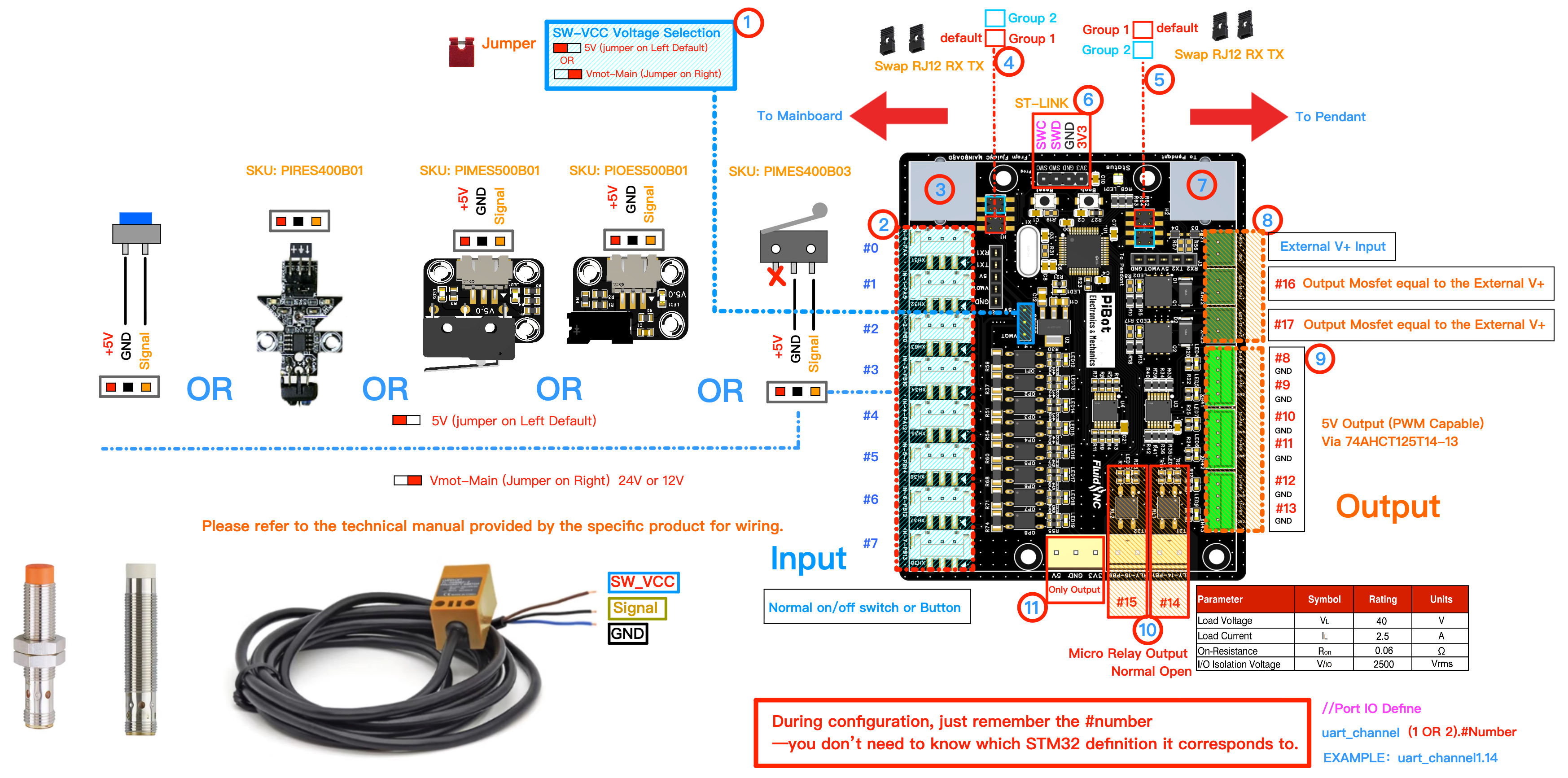
SW_VCC input-voltage jumper
Selects the field voltage used by all eight optocoupler inputs. Put the shunt on the 5 V side for 5 V devices and ordinary dry-contact wiring; put it on VMOT when the controller VMOT supply is 12 V or 24 V and the sensor is rated for that voltage.
Inputs #0–#7
Eight optocoupler input channels for limit switches, probes, buttons and compatible 3-wire sensors. Each channel uses the board's SW_VCC, Signal and GND arrangement shown on the PinMap. Dry contacts connect Signal to GND and leave the SW_VCC terminal unused; powered sensors must use an NPN (sinking / open-collector) output that pulls Signal down to GND.
uart_channel2.0 through .7, never as outputs.From FluidNC Mainboard
This RJ12 socket is the controller-side entrance. It carries the documented PiBot power and UART path from a V5.88/V5.77 direct socket or through the supplied 4.x adapter for V4.96/V4.7B.
Mainboard RX/TX swap jumpers
The two shunts select Group 1 or Group 2 for the UART pair coming from the controller. Start with Group 1, the default shown on the V5 PinMap. If power is present but communication fails after YAML/GPIO checks, power off and move both shunts together to Group 2.
Pendant RX/TX swap jumpers
A separate pair controls the downstream UART orientation to a Pendant V4.2 or compatible smart display. Start with Group 1. Evaluate Group 2 only when the expander itself works but the downstream device has no serial data.
STM32 ST-Link header
Recovery/programming header for 3V3, GND, SWDIO and SWCLK. It is used only when the normal preloaded firmware cannot be recovered through FluidTerm UART passthrough.
To Pendant
Downstream RJ12 socket for a compatible PiBot pendant or smart display after the expander is already communicating with the controller. The expander remains first in the chain.
External V and MOSFET #16/#17
The separate External V input supplies the two MOSFET output channels. Their load voltage follows External V; it does not come from VMOT or SW_VCC. Use these only for low-voltage DC loads with correct polarity.
Buffered 5 V outputs #8–#13
Six digital or PWM-capable 5 V signals buffered through the board's 74AHCT125 stage. Each is intended for a compatible logic, optocoupler, relay-module or driver input.
PhotoMOS relay outputs #14/#15
Two onboard normally-open solid-state switches with individual indicator LEDs. They are convenient for isolated low-voltage on/off control and are the channels used by the M7/M8/M9 example test in section 9.
Reserved output / voltage access
The lower output-only and voltage-access area is reserved for output use shown by the V5 PCB and schematic. It is not another general-purpose input and is not a substitute for the numbered #0–#17 terminals.
 4. I/O numbering and electrical working limits
#0–#7 · Inputs
Eight optocoupler inputs. SW_VCC selects 5 V or VMOT (12/24 V) for the complete bank.
#8–#13 · Logic/PWM
Six buffered 5 V signals. Connect to compatible logic inputs or an external driver stage.
#14–#15 · PhotoMOS
Two normally-open isolated switches with LEDs. Documentation limit: 1 A per channel, low voltage only.
#16–#17 · MOSFET
Two External-V DC outputs. Documentation limit: 24 V DC / 3 A per channel.
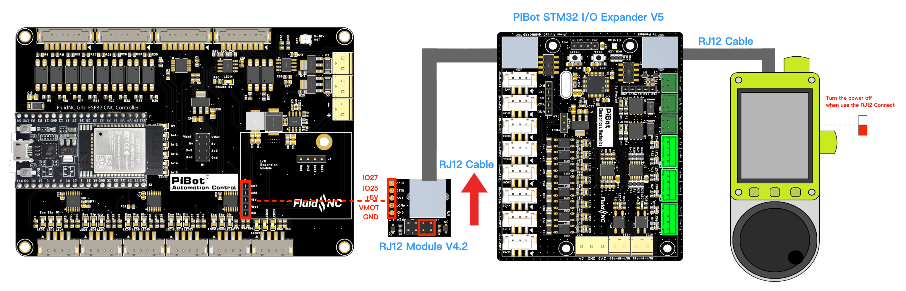
 5. Connect a PiBot controller
| Controller | UART | TX | RX | Controller-side path | Configuration note |
|---|---|---|---|---|---|
| V5.88 Ultra | UART2 | GPIO.0 | GPIO.35 | Direct PiBot RJ12 | OLED is independent. |
| V5.77 Carrier | UART2 | GPIO.0 | GPIO.35 | Direct PiBot RJ12 | Same expander mapping as V5.88; no separate GPIO.0 startup warning. |
| V4.96 Pro | UART2 | GPIO.27 | GPIO.25 | Supplied PiBot 4.x adapter | Disable OLED/I2C using GPIO.25/27. |
| V4.7B | UART2 | GPIO.27 | GPIO.25 | Supplied PiBot 4.x adapter | Disable OLED/I2C using GPIO.25/27. |
- Finish the controller's basic checklist before adding the expander.
- Turn off controller power, VMOT and External V; disconnect any pendant battery.
- Set SW_VCC for the planned 5 V or 12/24 V input devices.
- Connect the direct RJ12 socket or supplied 4.x adapter to From FluidNC Mainboard.
- Keep all external loads disconnected while configuring and testing the two SSR indicator LEDs.
- Upload the matching YAML block from section 7, select that configuration and complete section 9.
V5.88 Ultra → Expander V5 → Pendant
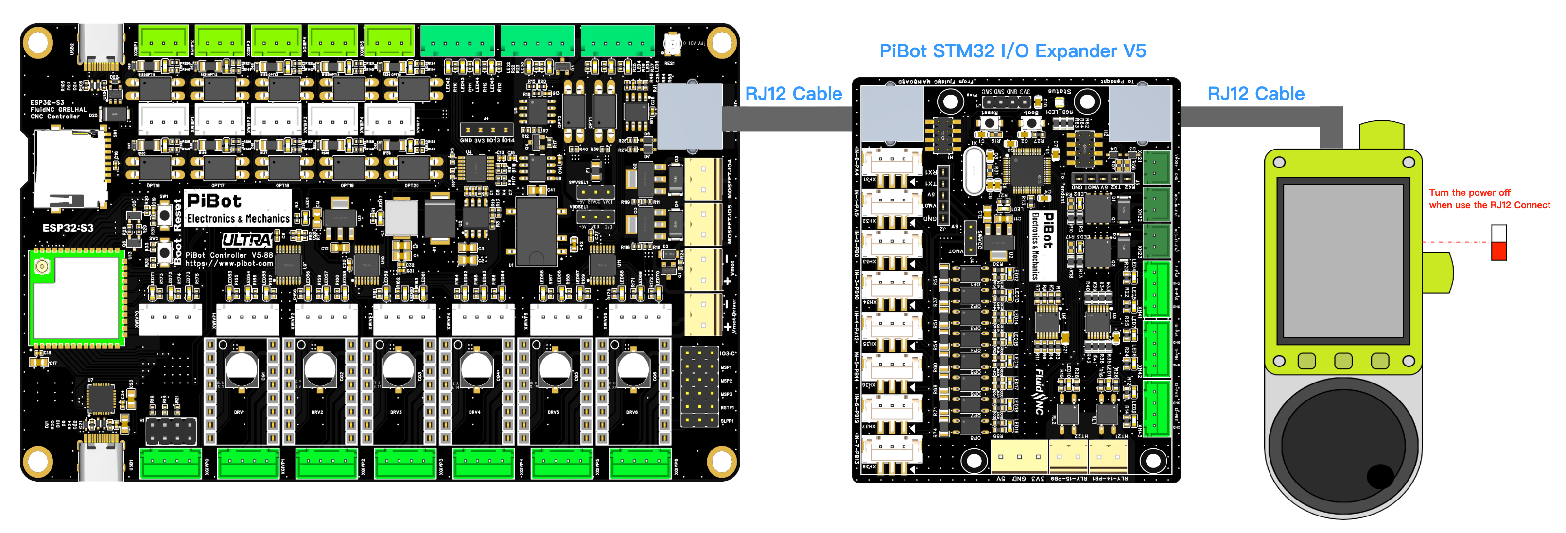
V5.77 Carrier → Expander V5 → Pendant
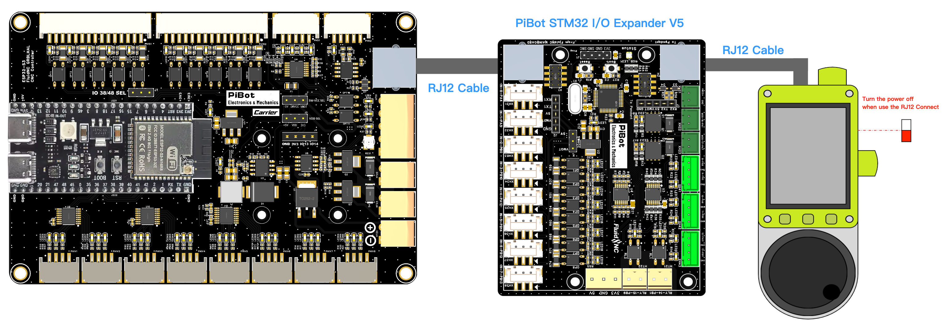
V4.96 Pro → 4.x Adapter → Expander V5
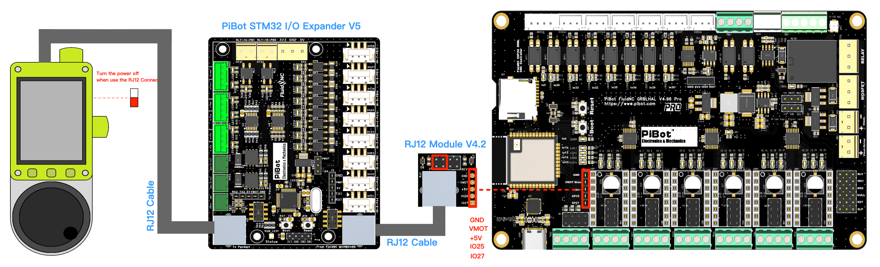
V4.7B → 4.x Adapter → Expander V5
 6. Set the two RX/TX jumper groups
Controller side · callout 4
Start with both shunts in Group 1, as shown on the PinMap. If the board is powered but the expander is not found, first confirm the active YAML, UART2, the correct controller GPIO pair and 1,000,000/8N1. Only then power off and move both shunts to Group 2.
Pendant side · callout 5
Leave Group 1 selected while testing the expander alone. After the expander passes, attach the pendant. If only the pendant lacks data, power off and evaluate Group 2 on this downstream jumper pair.
 7. FluidNC YAML for normal operation
"8N1". The 57,600/8E1 passthrough settings in section 12 are only for transferring STM32 firmware.V5.88 Ultra / V5.77 Carrier
uart2:
  txd_pin: gpio.0
  rxd_pin: gpio.35
  baud: 1000000
  mode: "8N1"

uart_channel2:
  report_interval_ms: 75
  uart_num: 2
V4.96 Pro / V4.7B
# Disable OLED/I2C on GPIO.25 and GPIO.27.
uart2:
  txd_pin: gpio.27
  rxd_pin: gpio.25
  baud: 1000000
  mode: "8N1"

uart_channel2:
  report_interval_ms: 75
uart_num: 2- Download or back up the machine's current YAML before editing it.
- Add the matching
uart2anduart_channel2blocks at the top level with correct indentation. - For V4.96/V4.7B, remove or disable the OLED/I2C block using GPIO.25/27.
- Upload the edited YAML through FluidNC WebUI, select it with
$Config/Filename=your-file.yamlif needed, then restart FluidNC. - Read the configuration messages and correct any duplicate pin, indentation or UART error before connecting loads.
 8. Assign expander channels to machine functions
The format is uart_channelN.pin. All four documented PiBot controllers use UART channel 2 for this connection, so their V5 examples use uart_channel2.
Input example
# Example inside an axis section
limit_neg_pin: uart_channel2.4:low
Use #0–#7 only. Add :low only when the real input circuit must be active-low.
SSR test example
coolant:
  mist_pin: uart_channel2.14
  flood_pin: uart_channel2.15
This top-level block is used by the formal output test in section 9.
Output example
# Example configurable output
user_outputs:
  digital0_pin: uart_channel2.8
Use only a function supported by the installed FluidNC version and a channel of the correct electrical type.
 9. Configure and test M7/M8 outputs
This is the first functional test after the UART connection is configured. It checks the controller-to-expander path and the two onboard SSR channels using only their indicator LEDs; no external load is required.
9.1 Add the test configuration
- Keep #14/#15 load terminals empty.
- Add the following
coolantblock at the top level of the active YAML. - Upload/select the YAML and restart FluidNC.
- Confirm the configuration loads without an error.
coolant:
  mist_pin: uart_channel2.14
  flood_pin: uart_channel2.15
9.2 Send the commands
Open the FluidNC WebUI command box or FluidTerm and enter these commands one at a time:
mist_pin.flood_pin; #14 may remain on until M9. PASS · Test completed
 FAIL · Do not connect a real load
uart_channel2, the From Mainboard socket and one RX/TX swap point. For V4.96/V4.7B, also confirm OLED GPIO.25/27 is disabled. 10. Connect and verify inputs #0–#7
Dry-contact switch or button
- Power off and select 5 V at SW_VCC.
- Wire the contact between Signal and GND; leave that input's SW_VCC terminal unconnected.
- Assign the matching
uart_channel2.Ninput in a backup YAML. - With machine motion disabled, operate the contact and confirm the FluidNC input changes state.
Powered 3-wire NPN sensor
- Confirm the sensor is NPN (sinking / open-collector) and check its rated supply in its own manual.
- Select 5 V or VMOT (12/24 V) before connecting it.
- Connect sensor V+ to SW_VCC, GND/reference to GND, and the NPN output to Signal.
- Test one sensor with motion disabled, correct YAML polarity if required, then repeat for other channels.
 11. Connect the three output groups
#8–#13 · Buffered 5 V
- Digital or PWM-capable logic signals.
- Connect Signal and GND to a compatible control input.
- Use an external relay/driver module for a coil or higher-current load.
- Measure the unloaded state before connecting the controlled device.
#14/#15 · PhotoMOS relay
- Normally-open isolated low-voltage switches.
- Each channel has a local state LED.
- Documentation limit: 1 A/channel, at or below 24 V DC / 12 V AC for extra margin.
- Do not use for mains voltage.
#16/#17 · External V MOSFET
- For low-voltage DC loads only.
- Supply comes from the separate External V terminal, not VMOT.
- Documentation limit: 24 V DC / 3 A per channel.
- Observe polarity and add suppression for inductive loads.
 12. STM32 firmware download and recovery
Method A · FluidTerm UART passthrough
For recovery only, add the passthrough lines under the same controller UART:
uart2:
  txd_pin: gpio.0       # gpio.27 on V4.96/V4.7B
  rxd_pin: gpio.35      # gpio.25 on V4.96/V4.7B
  baud: 1000000
  mode: "8N1"
  passthrough_baud: 57600
  passthrough_mode: "8E1"

uart_channel2:
  report_interval_ms: 75
  uart_num: 2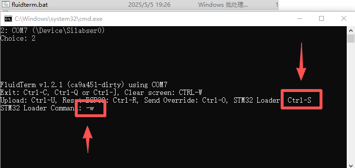
Upload sequence
- Back up the working YAML and enable passthrough.
- Open FluidTerm and select the controller serial port.
- Press CTRL+S, choose the supplied STM32
firmware.binand enter-W. - Hold BOOT0, press and release RESET, then release BOOT0.
- Complete the transfer, reset normally, restore the normal YAML if desired and repeat section 9.
Method B · ST-Link recovery
| ST-Link | Expander V5 header | Check |
|---|---|---|
| 3.3V | 3V3 | Never use 5 V on this header. |
| GND | GND | Common reference. |
| SWDIO | SWD | Verify label before power. |
| SWCLK | SWC | Verify label before power. |
- Disconnect controller RJ12, VMOT, External V and all loads.
- Connect the four verified 3.3 V ST-Link signals.
- Program only the PiBot-supplied common expander image.
- Disconnect the programmer, restore normal power and repeat section 9.
 13. Connect Pendant V4.2 downstream
- Complete the expander's M7/M8/M9 test without the pendant.
- Power off and connect the pendant to To Pendant, not to the controller-side socket.
- Use the pendant firmware/settings for the documented 1,000,000-baud wired path.
- Start with the expander pendant-side jumpers in Group 1.
- Power on with motors, spindle and laser disabled; confirm both expander I/O and pendant data update.
- If only the pendant lacks data, power off and change exactly one downstream RX/TX correction point.
 14. grblHAL support (advanced)
Current grblHAL sources include an experimental FluidNC I/O Expander plugin that uses the FluidNC Channel I/O protocol. It can expose up to eight digital inputs and ten outputs, including compile-time PWM-output support.
- The selected grblHAL driver/board build must provide an unused hardware UART.
- Enable the plugin at build time with
FNC_EXPANDER_ENABLE 1. - Select analog/PWM output count with the plugin's
FNC_N_AOUTbuild setting. - Do not reuse FluidNC YAML as a grblHAL configuration; build and test the exact controller target.
 grblHAL miscellaneous plugins
 grblHAL changelog
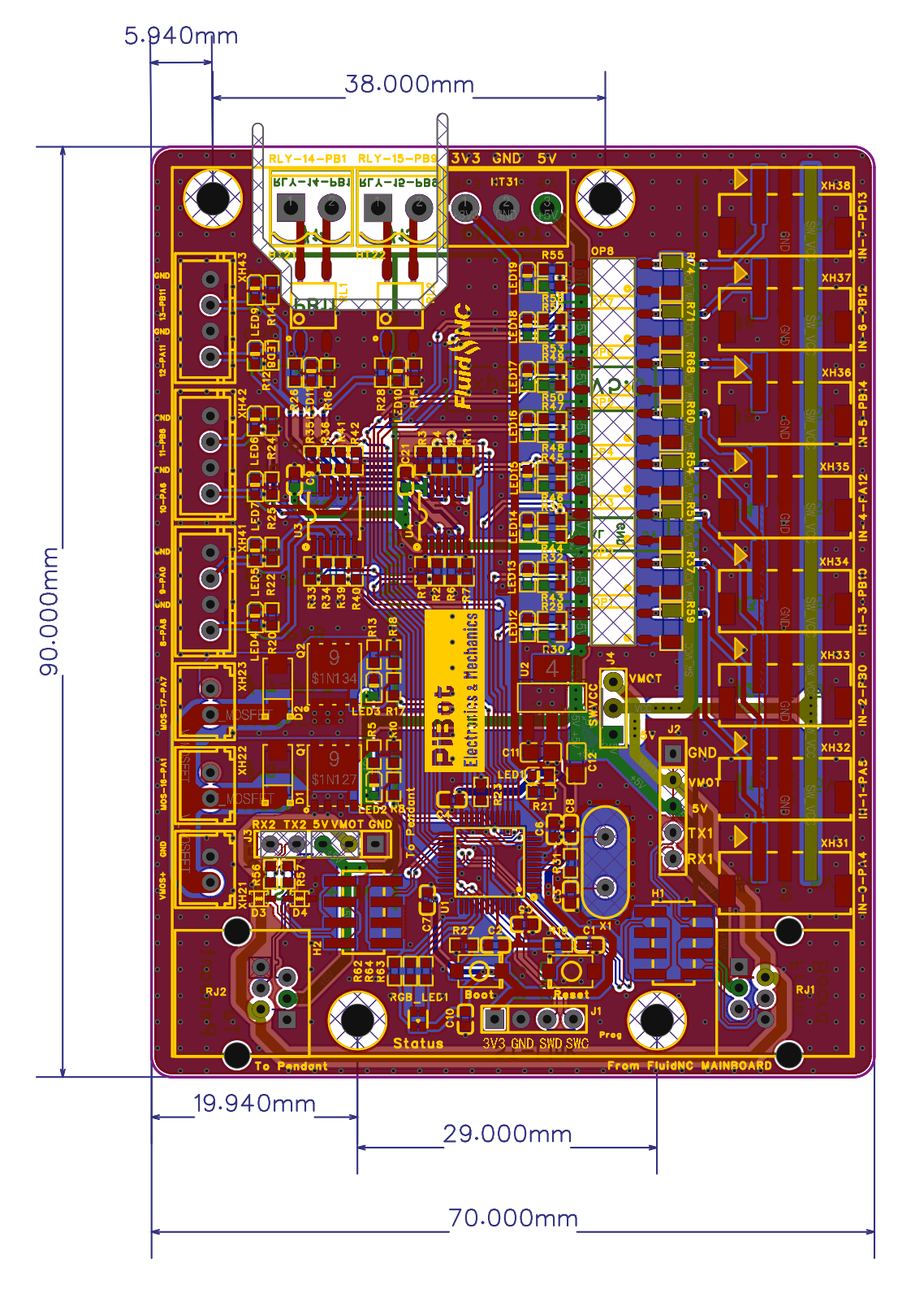
 15. Size, downloads and source documents
The dimension drawing includes the mounting-hole centres and edge offsets. Use the original drawing when designing an enclosure or mounting plate.
 16. Troubleshooting
No power or status indication
- Power off immediately.
- Disconnect pendant and every external load.
- Verify the PiBot controller/adapter path and cable orientation.
- Do not move power pins while troubleshooting serial direction.
Power present, no communication
- Confirm active YAML, UART2, correct GPIO pair and 1,000,000/8N1.
- Confirm the cable uses From FluidNC Mainboard.
- For V4.96/V4.7B, disable OLED on GPIO.25/27.
- Power off and change one mainboard-side RX/TX group.
SSR LEDs do not follow commands
- Confirm
coolantmaps #14/#15. - Confirm
uart_channel2is the active channel. - Send M9, correct the YAML and repeat section 9.
- Do not connect a load until the LED test passes.
Expander works, pendant does not
- Use To Pendant and disconnect the battery.
- Match the wired firmware and baud.
- Keep the expander mainboard jumpers unchanged.
- Power off and change one downstream RX/TX correction point.
