
PiBot CNC Pendant V4.2 Complete Manual
A capacitive-touch, encoder-based hand controller for compatible FluidNC systems. Use ESP3D for the actively maintained PiBot workflow, or FluidDial for the current ESP-NOW workflow. Both firmware families also support wired RJ12 serial communication.
1. Product overview
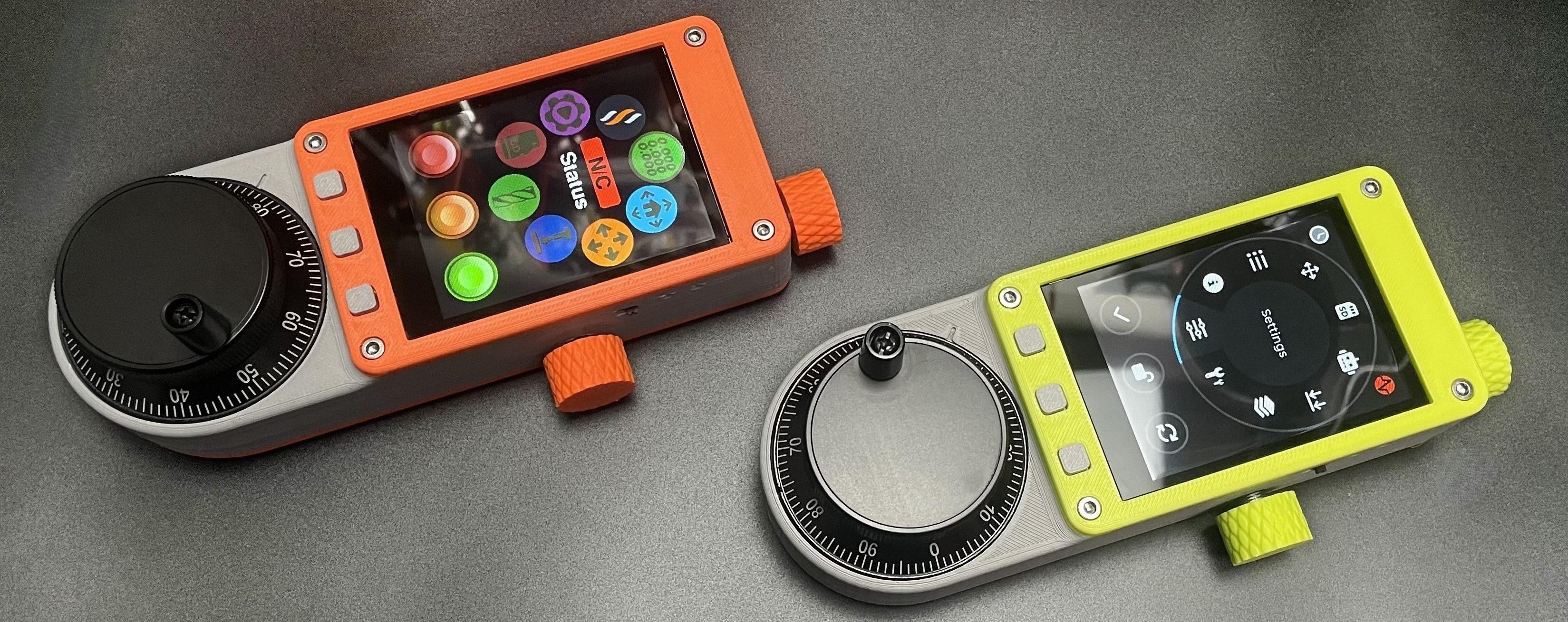
PiBot designed the electronics after testing other touch-screen and encoder combinations that did not provide the required control feel. The result combines a responsive capacitive touch screen, an industrial-style handwheel encoder and dedicated physical controls in a compact enclosure. PiBot develops and maintains the ESP3D-based product workflow with Luc, the author of ESP3D. The enclosure design was contributed by Liz W. in the United States, and FluidDial provides the alternative open-source firmware family.
What V4.2 adds
- Two physical jumper groups for swapping UART RX and TX without opening or re-pinning the cable.
- Improved automatic-download circuit: normal USB installation no longer requires holding and releasing BOOT.
- 18650 reverse-polarity protection.
- Updated V02 enclosure with a small cover beside the battery compartment.
Compatible control systems
- PiBot V5.88 Ultra
- PiBot V4.96 Pro
- PiBot V5.77 Carrier
- PiBot V4.7B
- Other FluidNC controllers only when their UART pinout, supply, baud rate and firmware feature set are confirmed compatible.
2. Package contents
A. Pendant V4.2
Fully assembled main unit.
B. RJ12 Adapter V4.2
Controller-side conversion module with a physical RX/TX selection jumper.
C. RJ12 cable
One approved 1 m communication cable.
3. Hardware features and specifications
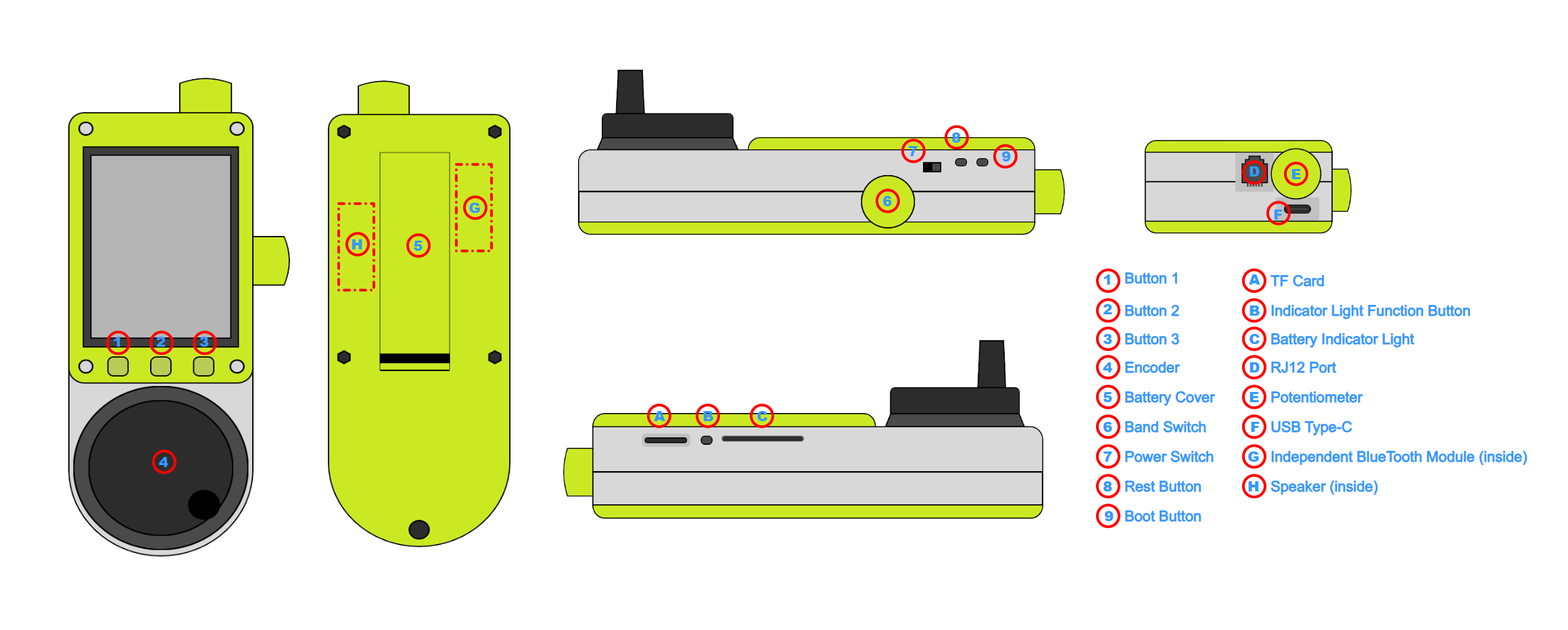
Controls and interfaces
- Capacitive touch screen
- Industrial-style rotary encoder/handwheel
- Potentiometer knob and band/selector switch
- Three independent push buttons
- Built-in speaker
- RJ12 wired serial connection
- USB connection for firmware installation
- Dual-PCB design with internal expansion access
Mechanical and battery
- Weight: approximately 365 g
- Body size: approximately 165 × 60 mm
- Screen area: approximately 76 × 55 mm
- Battery: one flat-top 18650 cell; Sony VTC5/VTC6 used for PiBot testing
- Battery level display, charging and reverse-polarity protection
- V01 original and V02 updated printable enclosure archives available below
4. Choose the firmware and connection method
| Firmware | Wireless method | Wired method | Recommended use |
|---|---|---|---|
| ESP3D PiBot firmware | Wi-Fi | RJ12 UART | Recommended and primarily maintained by PiBot. Includes the software Swap RX TX setting. |
| FluidDial for PiBot | ESP-NOW | RJ12 UART | Alternative open-source interface. PiBot provides a compiled online installer and a PiBot source branch. |
| Legacy ESP3D / old FluidNC | Built-in Bluetooth on supported old configurations | RJ12 UART | Legacy only. Not recommended for a new installation; no external Bluetooth-module tutorial is provided. |
| grblHAL | Pendant firmware support is still under development. | Do not use the FluidNC instructions as a grblHAL procedure. | |
5. Install or update pendant firmware
Option A — ESP3D Recommended
Use the official ESP3D browser installer and select the PiBot pendant target described by the installer.
Option B — FluidDial ESP-NOW
Use the PiBot web installer for the ready-to-flash build, or compile the PiBot source target with VS Code and PlatformIO.
USB installation sequence for Pendant V4.2
Compile FluidDial from source (advanced)
The PiBot branch already contains PiBot pendant hardware support. In VS Code with PlatformIO, use the current environment names shown by the checked-out source. The PiBot release branch documents merged builds for 1,000,000 and 115200 baud; build the variant that matches the intended wired configuration, then flash the merged image at offset 0x0. Users following the newest upstream FluidDial may ask their coding assistant to select or recreate the PiBot Pendant V4 hardware target before building.
6. Wireless setup
ESP3D over Wi-Fi
- Install the current ESP3D PiBot firmware.
- Open the pendant network/connection settings.
- Connect the pendant to the network used by the FluidNC controller, or to the controller's documented access point.
- Enter the FluidNC host/IP required by the ESP3D firmware.
- With motors and the spindle/laser disabled, confirm status updates and one jog axis at a safe distance.
Use the linked ESP3D PDF for the exact current screen names and settings.
FluidDial over ESP-NOW
- Install the current PiBot FluidDial ESP-NOW build.
- Make sure the controller uses a PiBot FluidNC build that supports the matching ESP-NOW pendant channel.
- Select ESP-NOW in the pendant connection settings and open the pairing screen.
- Open the pairing window on the controller; current implementations use
$espnow/pairin a FluidNC terminal. - Wait for both sides to save the pairing, then perform the safe-function check below.
If the controller firmware does not expose ESP-NOW pairing, update it using the instructions for that exact PiBot board rather than substituting another model's firmware.
7. RJ12 wired connection — read before wiring
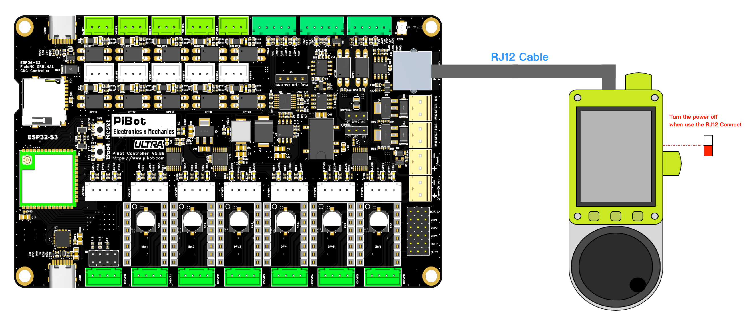
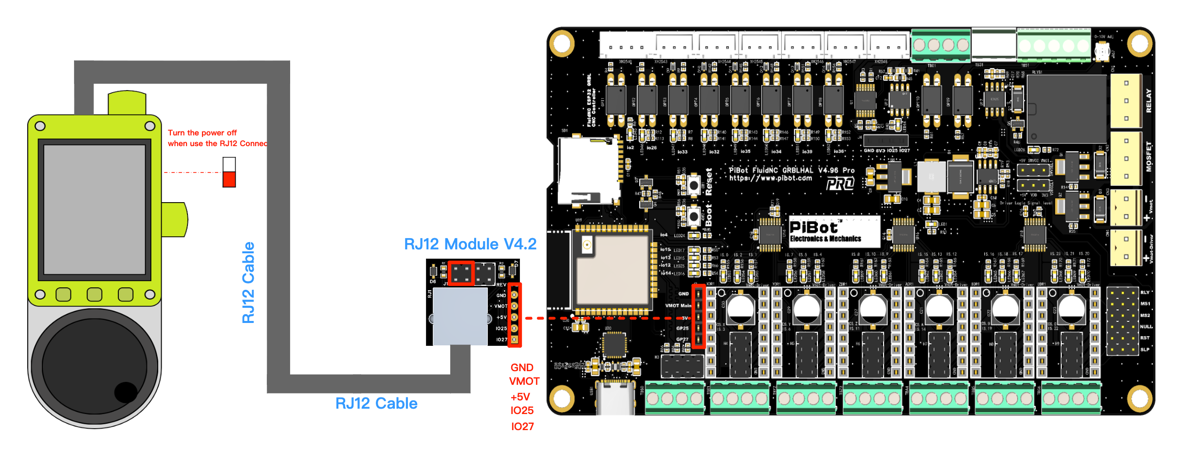
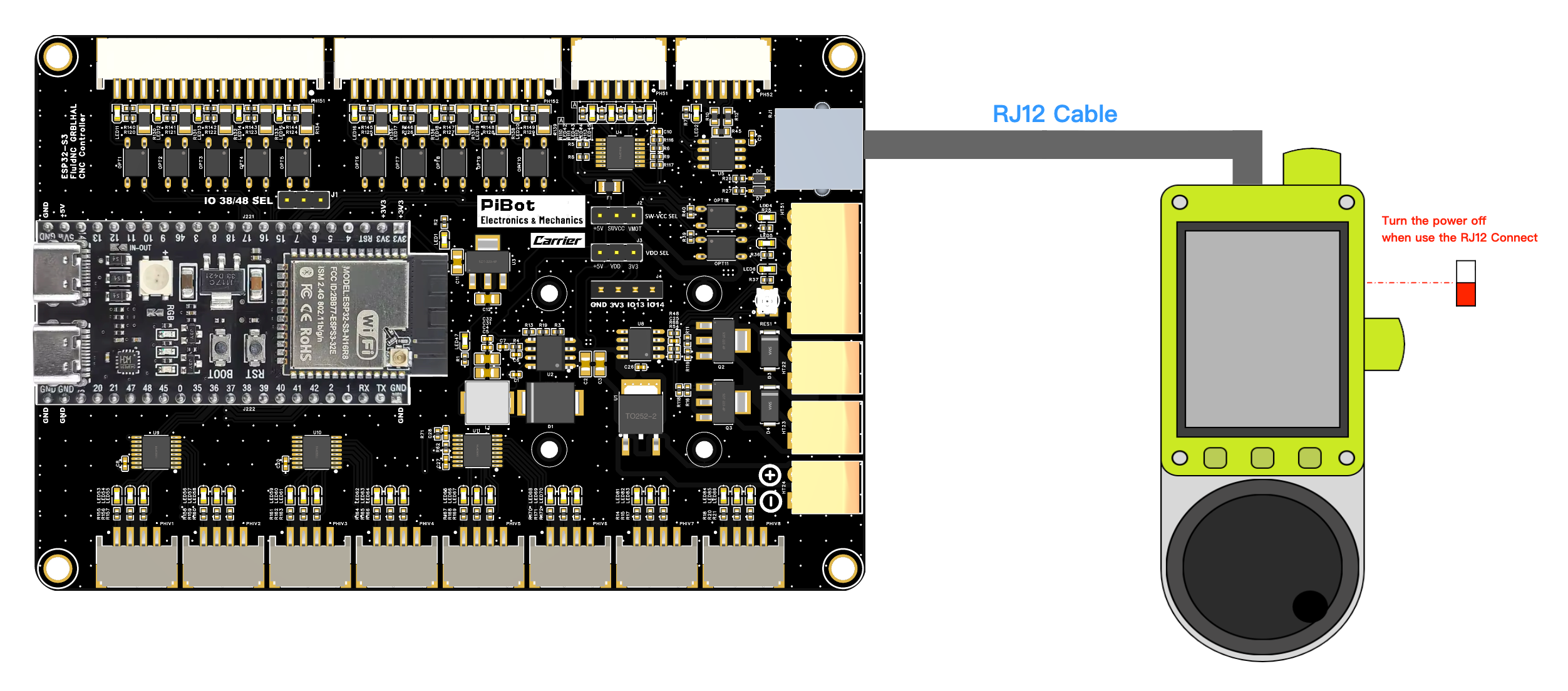
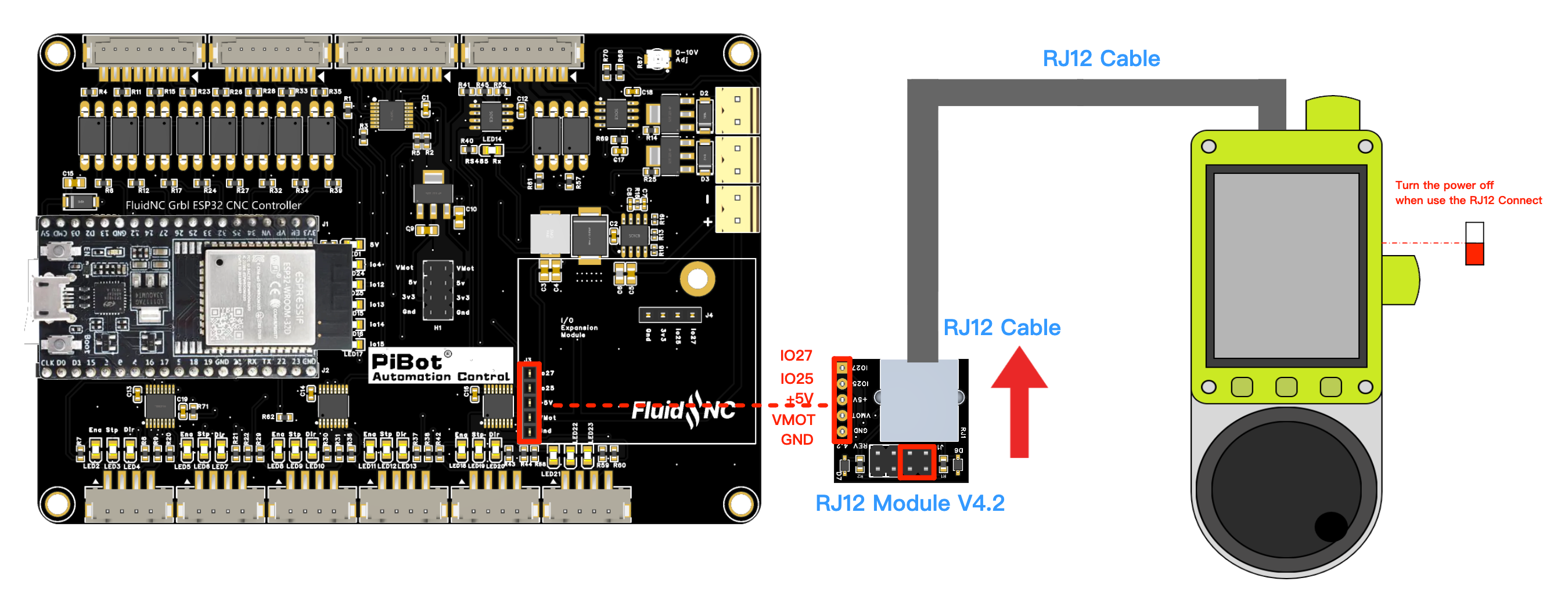
- Turn off controller and machine power before plugging or unplugging any RJ12 cable or adapter.
- Move the pendant battery switch down. The 18650 may remain physically in its holder only while the switch keeps it electrically disconnected.
- Use the supplied PiBot RJ12 cable. A telephone handset cable may fit while using a different contact order.
- Set the pendant firmware to wired/serial mode and match the controller UART baud rate. The current direct and Expander V5 examples use
1000000 8N1. - Use only one RX/TX swap method in the complete chain.
- After wiring, power the controller, inspect its boot log and test the pendant with motors, spindle and laser disabled.
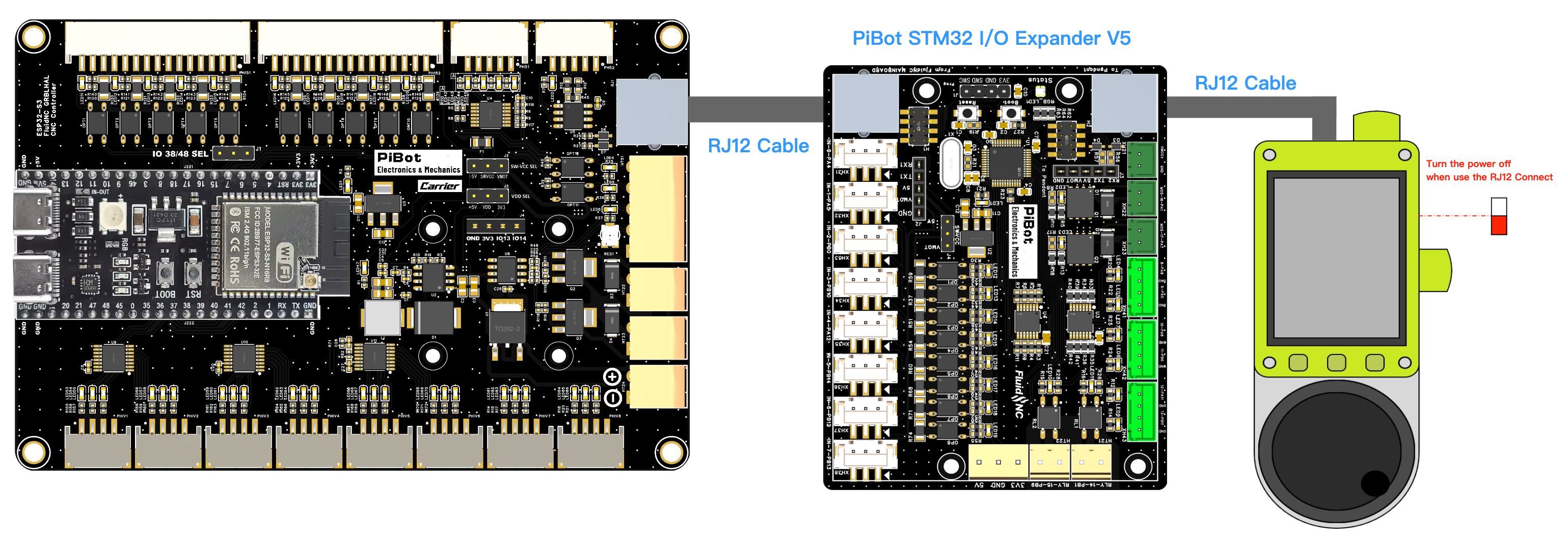
8. Direct RJ12 connection to PiBot controllers
V5.88 Ultra
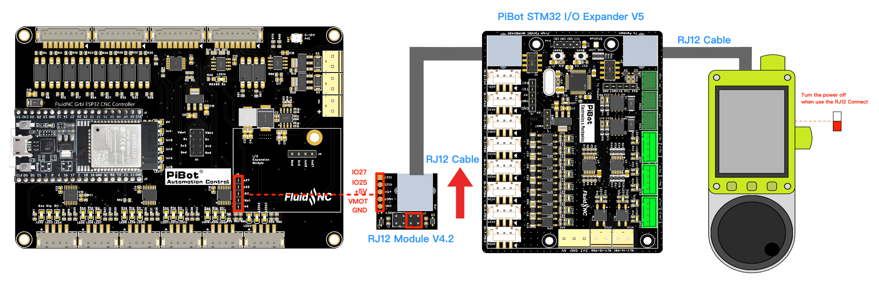
V4.96 Pro with RJ12 Adapter V4.2
V5.77 Carrier
V4.7B with RJ12 Adapter V4.2
9. Connect through PiBot I/O Expander V5
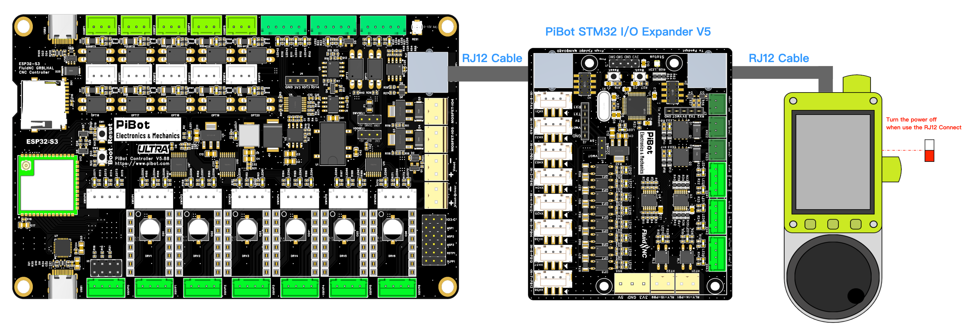
V5.88 Ultra → Expander V5 → Pendant
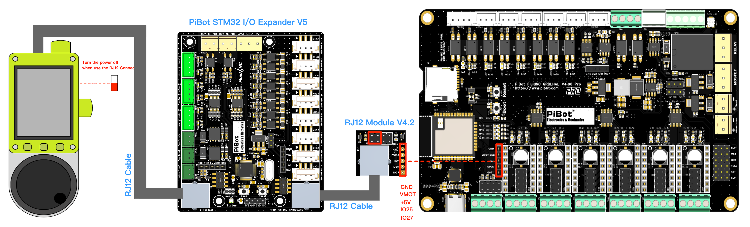
V4.96 Pro → RJ12 Adapter V4.2 → Expander V5 → Pendant
V5.77 Carrier → Expander V5 → Pendant
V4.7B → RJ12 Adapter V4.2 → Expander V5 → Pendant
10. RX/TX direction and jumper selection
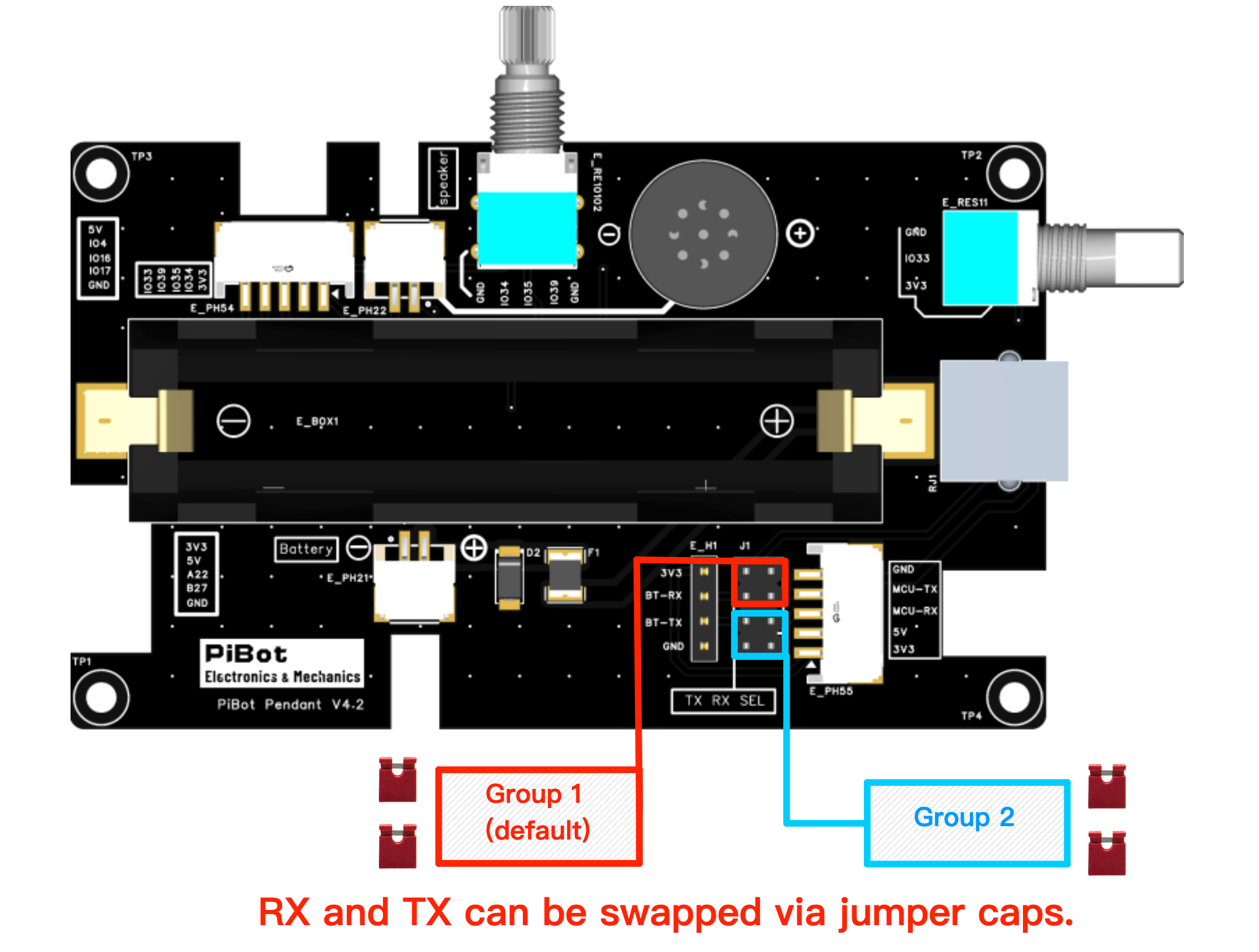
| Correction point | Available method | Rule |
|---|---|---|
| Pendant V4.2 | Move both jumper caps from Group 1 to Group 2, or back to Group 1. | Move only with all power removed. |
| RJ12 Adapter V4.2 | Use its physical RX/TX jumper group. | Useful for V4.96 and V4.7B controller-side correction. |
| I/O Expander V5 | Use one of its documented RX/TX jumper groups. | Choose one correction point in the whole chain. |
| ESP3D firmware | Settings → Setting Editor → Swap RX TX | Software swap can replace a physical swap; do not enable both. |
| Older pendant/cable | Exchange only the confirmed RX and TX contacts in the detachable signal cable. | Legacy fallback only; never move power or GND. |
11. FluidNC UART configuration
The physical RX/TX correction options are shared, but GPIO numbers are not. Start with the YAML and RJ12 test page for the exact controller model.
| Controller | Direct UART2 mapping | Default documented baud | Resource conflict / note | Exact test page |
|---|---|---|---|---|
| V5.88 Ultra | TX GPIO.0RX GPIO.35 | 1000000 8N1 | RJ12 and OLED use independent pins and may operate together. | V5.88 Test RJ12 |
| V4.96 Pro | TX GPIO.27RX GPIO.25 | 1000000 8N1 | OLED shares GPIO.25/27; disable OLED when UART2 is used. | V4.96 Test RJ12 |
| V5.77 Carrier | TX GPIO.0RX GPIO.35 | 1000000 8N1 | GPIO.0 is a boot-strap pin; disconnect the accessory for diagnosis if boot fails. | V5.77 Test RJ12 |
| V4.7B | TX GPIO.27RX GPIO.25 | 1000000 8N1 | OLED shares GPIO.25/27; disable OLED when UART2 is used. | V4.7B Test RJ12 |
UART channel pattern
Replace the two GPIO values only with those confirmed for the selected board. Do not copy a V5.88/V5.77 mapping into V4.96/V4.7B or vice versa.
uart2:
  txd_pin: gpio.<BOARD_TX>
  rxd_pin: gpio.<BOARD_RX>
  rts_pin: NO_PIN
  cts_pin: NO_PIN
  baud: 1000000
  mode: 8N1

uart_channel2:
  report_interval_ms: 75
  uart_num: 2
12. First safe-function test
- The machine's hard-wired E-stop has been tested independently.
- Spindle/laser enable and motor power are disabled for the pendant test.
- Wireless pairing or UART connection survives a cold boot.
- Displayed machine state and coordinates update without repeated connection errors.
- Each physical button performs only its labelled function.
- The encoder changes the selected value/axis in the intended direction.
- A short, low-speed jog moves only the selected axis and stops when released.
- Feed hold, cycle start and reset produce the expected FluidNC state.
13. Troubleshooting
USB installer cannot connect
- Use Chrome/Edge and a data-capable USB cable.
- Close serial monitors and other programs using the port.
- Retry another USB port and lower flashing speed.
- Confirm the battery switch is down and RJ12 is removed.
- V4.2 should auto-download; use BOOT recovery only if specifically required.
Wireless has no connection
- Confirm the installed firmware family: ESP3D uses Wi-Fi; current FluidDial uses ESP-NOW.
- For ESP-NOW, confirm the controller firmware supports the matching channel and repeat pairing.
- For ESP3D, confirm network credentials and the FluidNC host/IP.
- Do not follow the retired external Bluetooth-module pairing tutorial.
RJ12 has power but no data
- Confirm identical baud rates.
- Confirm board-specific TX/RX GPIOs and the active YAML filename.
- Change exactly one RX/TX swap point.
- For V4.96/V4.7B, verify OLED is disabled.
- Use only the approved cable and correct adapter orientation.
Direct works; Expander path fails
- Test the pendant directly and the Expander separately.
- Confirm “From FluidNC Mainboard” and “To Pendant” ports are not reversed.
- Match the controller, expander and pendant baud rates.
- Use one Expander/adapter/pendant jumper as the RX/TX correction point.
14. Developer reference
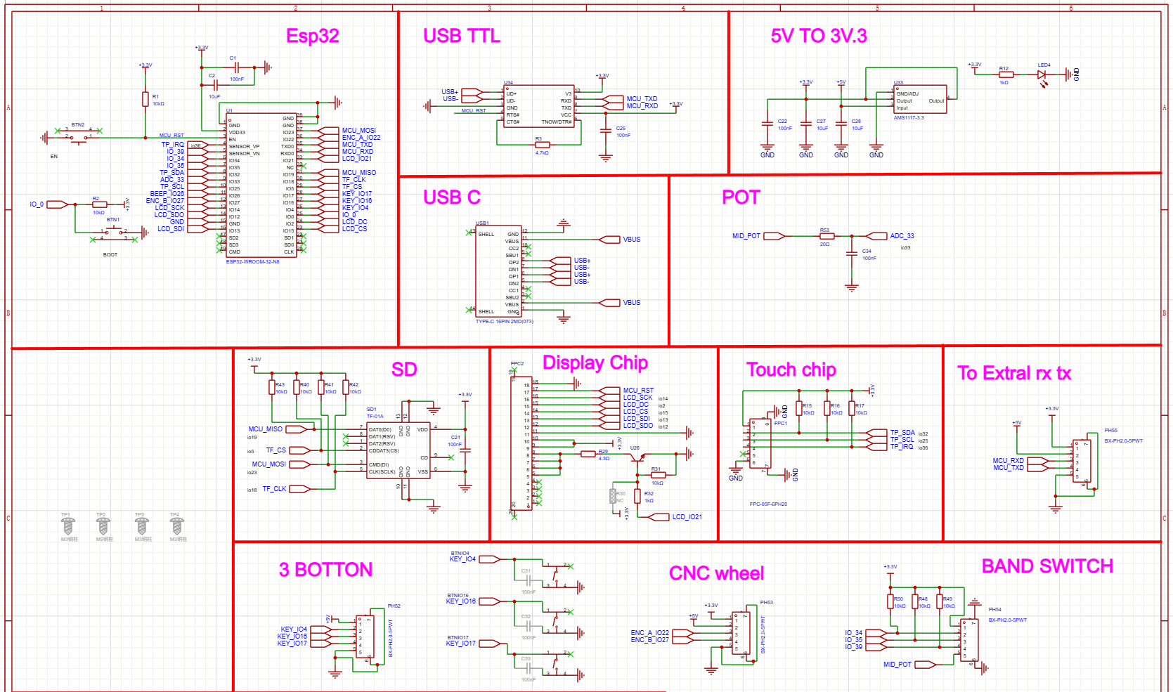
ILI9341 display
TFT_CS   15
TFT_DC    2
TFT_MOSI 13
TFT_CLK  14
TFT_MISO 12
TFT_RST  -1
TFT_LED  21
FT6336U touch
TOUCH_SDA 32
TOUCH_SCL 25
TOUCH_IRQ 36
TOUCH_CS  33
Other peripheral pins
- Potentiometer centre tap: GPIO.26
- TF/microSD: MISO GPIO.19, CS GPIO.5, MOSI GPIO.23, CLK GPIO.18
- Buttons: GPIO.4, GPIO.16 and GPIO.17, active low
- Encoder: GPIO.22 phase A, GPIO.27 phase B
- Three-position switch: GPIO.34, GPIO.35 and GPIO.39 with pull-ups
Power-controller indicator button
- More than 50 ms but less than 2 s: short press; enables the battery indicator and boost output.
- More than 2 s: long press; toggles the LED light.
- Less than 50 ms: ignored.
- Two short presses within 1 s: turns off boost output, battery indicator and LED light.
15. Downloads and support
V01 original enclosure: contains the original battery lid, case top and bottom, button, spacer, handwheel/roller part and potentiometer knob files.
V02 updated enclosure: retains the newer case parts, including the battery-area lid/cover, case top and bottom variants, joined spacers, two knobs and PiBot buttons. Both revisions remain available so existing builds are not forced onto the newer shell.
ESP3D support: Join the PiBot Discord and use the Pendant support thread.