2.8 Test MOSFET Output
Check List · Step 8 of 12 · Measure each MOSFET terminal switching 0 V ↔ 24 V
🎯 Objective
The board has two MOSFET outputs, io.4-MOS-GND and io.5-MOS-GND. You'll switch each one on and off and confirm its terminal swings between 0 V and about 24 V with a multimeter, while its indicator LED follows along. This is the first step that uses the multimeter — take it slowly.
🔌 How it works: each output is a low-side MOSFET. The pin name
io.4-MOS-GND tells you it is the GND side that output io.4 switches. In normal use your load wires between Vmot-Main (+) and io.X-MOS-GND; turning the output ON connects io.X-MOS-GND to GND, so the full motor voltage (Vmot, ~24 V) appears across the load. With no load attached, the multimeter reads that voltage straight across the two terminal pins — about 0 V when off, ~24 V when on.
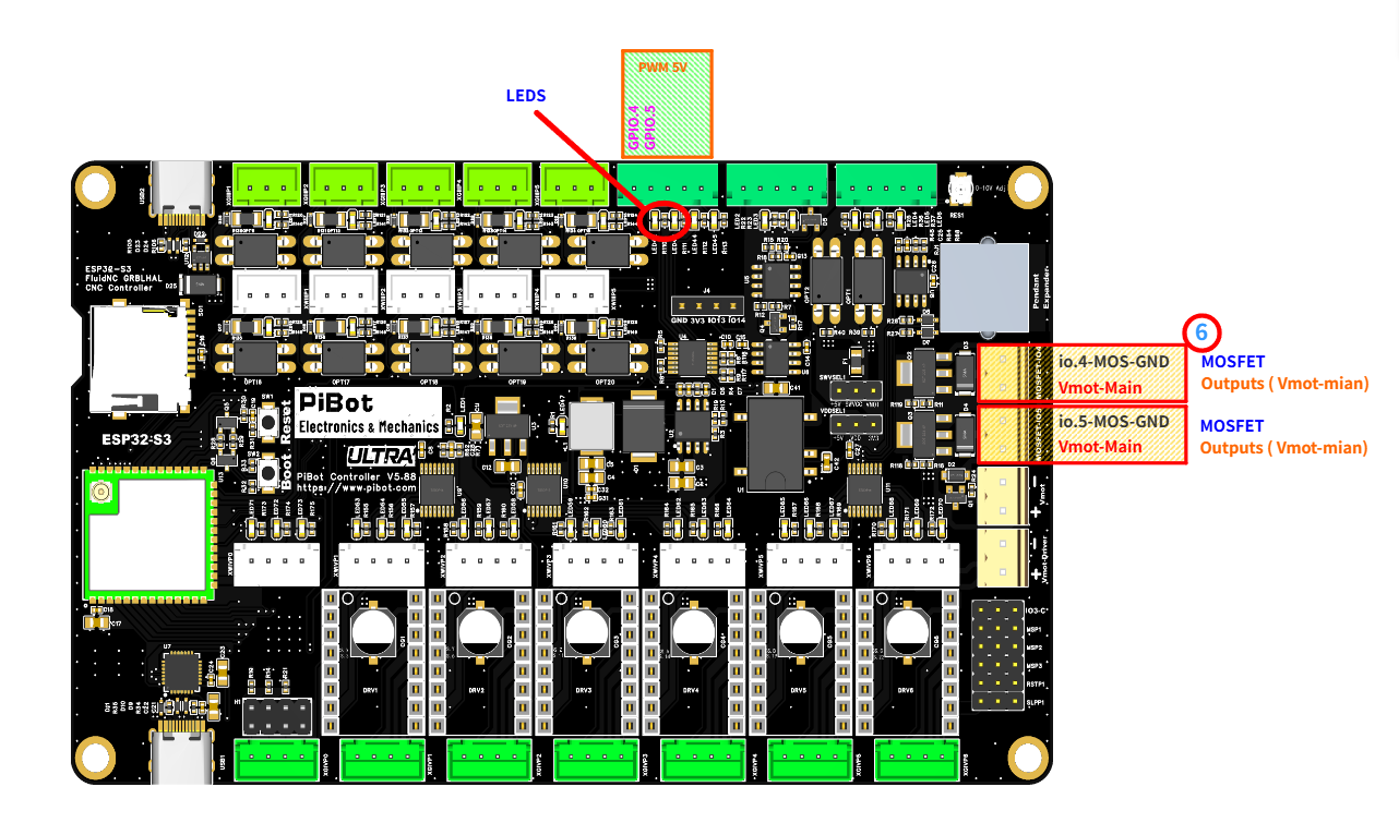
The two MOSFET terminals (right, orange) — each has an io.X-MOS-GND pin (top) and a Vmot-Main pin (bottom) — and their indicator LEDs (red circle, GPIO.4 / GPIO.5). (click to enlarge)
🔧 How to Measure
Set the multimeter to DC voltage, auto-range. On the orange io.4-MOS-GND terminal, put the probes across its two pins — top pin and bottom pin, exactly as in the photo:
RED (+) → Vmot-Main (bottom)
BLACK (−) → io.4-MOS-GND (top)
With nothing switched on it reads about 0 V. (If the meter shows a minus sign, your probes are reversed — just swap them.)
Output 0 —
io.4-MOS-GND terminal
M64 P0
→
24.0 VGPIO.4 LED on
M65 P0
→
0.0 VLED off
👈 Now move both probes to the io.5-MOS-GND terminal — same way: RED (+) on Vmot-Main (bottom), BLACK (−) on io.5-MOS-GND (top).
Output 1 —
io.5-MOS-GND terminal
M64 P1
→
24.0 VGPIO.5 LED on
M65 P1
→
0.0 VLED off
✅ Pass: each terminal reads about 24 V (LED on) with
M64 and drops back to about 0 V (LED off) with M65. If both do, the MOSFET outputs are good.⚠ Careful: Vmot-Main carries the full motor voltage (~24 V) and each output switches up to 500 mA. Don't let the two probe tips touch each other, and keep stray wire strands away from the terminal.