4.1 Connect Limit Switches
The V5.88 Ultra has 10 optocoupler-isolated inputs (OPT11–OPT20) arranged in two rows along the top edge. All ten channels are electrically identical, and every input header carries the same three pins: Signal / GND / SW-VCC.
- The board sources the current, not your sensor. Current leaves SW-VCC, passes through the on-board resistor and the optocoupler LED, and exits at the Signal pin. An input triggers only when your device pulls Signal down to GND.
- No external resistor is needed — not even at 24 V. Each channel already carries its own 2.2 kΩ series resistor (R130–R139) on the board.
- Wrong polarity will not damage the board. A 30 V Schottky diode (RB521S-30) sits in series with every channel and blocks reverse current, so putting a positive voltage on a Signal pin simply fails to trigger instead of destroying the optocoupler. That covers any voltage this board can itself supply; never feed a Signal pin from a separate supply above 30 V.
- The SW-VCC rail feeds all ten optocouplers, so the jumper must always sit in one of its two positions — even when you only use dry contacts.
Input map in the test YAML
| Terminal | Assigned function | Terminal | Assigned function |
|---|---|---|---|
| GPIO.42 | X limit − | GPIO.41 | X limit + |
| GPIO.40 | Y limit − | GPIO.39 | Y limit + |
| GPIO.38 | Z limit − | GPIO.37 | A limit − |
| GPIO.36 | B limit − | GPIO.48 | C limit − |
| GPIO.47 | Probe | GPIO.3 | Toolsetter (jumper-selected) |
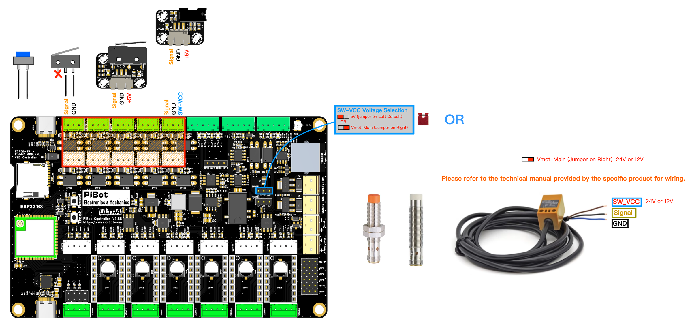
Any dry-contact switch or button: no polarity, no supply, just an open/closed contact. Works on every one of the ten inputs.
- Leave the SW-VCC jumper at its default 5 V position.
- Wire the switch between the Signal pin and the GND pin. Only two wires are used — leave the SW-VCC pin of that header unconnected.
- Prefer the normally-closed contact where practical, so a broken wire shows up as a triggered endstop instead of a dead one.
- Match the YAML polarity to the contact you chose, then confirm with $limits.
motor0:
  limit_neg_pin: gpio.42:low
  limit_pos_pin: gpio.41:low
A powered endstop repeats far more precisely than a bare micro switch. The PiBot Optical Endstop V5 and Mechanical Endstop V5 are built for this input: when triggered, their output pulls Signal down to GND, which is exactly what the optocoupler needs.
- Set the SW-VCC jumper to 5 V (left position, factory default).
- Sensor +5V → SW-VCC pin.
- Sensor Signal → Signal pin.
- Sensor GND → GND pin.
- Check the module LED and the matching board input LED, then verify with $limits.
Inductive and capacitive proximity sensors give the best noise immunity on larger machines. They run from the same Vmot-main rail that feeds the motors.
- Set the SW-VCC jumper to Vmot-Main (right position).
- Power the controller from the 12 V or 24 V supply the sensor needs. Vmot-main and SW-VCC must never exceed 24 V.
- Sensor brown / V+ → SW-VCC pin, blue / V− → GND pin, black / output → Signal pin.
- Verify each sensor with $limits before it is anywhere near a moving axis.
NPN sensors — use these
An NPN (sinking) output pulls Signal down to GND when it triggers, completing the optocoupler loop. Both NO and NC variants work; set the YAML polarity to match.
PNP sensors — not compatible
A PNP (sourcing) output pushes V+ into Signal. Because the optocoupler LED is already fed from SW-VCC, there is then no voltage across it and the input cannot trigger. The board is not damaged — the series Schottky absorbs the reverse voltage, so the input simply never responds.
motor0:
  limit_neg_pin: gpio.40:low
  limit_pos_pin: gpio.39:low
- Dry contacts mix with anything. They draw no supply of their own, so standard switches can share the board with either a 5 V or a 12–24 V group.
- 5 V and 12–24 V powered sensors cannot be used together on this board, because they would need two different SW-VCC settings at once.
- If you really need both, power the second group from its own suitable supply, leave those sensors' SW-VCC pins unconnected, and join grounds only where the equipment design permits. When in doubt, use isolated interface modules.
- Every input reads inactive at rest, changes state only when its own switch is operated, and returns cleanly when released.
- The matching input LED on the board follows each trigger.
- Run the bench test in 2.5 Test Probe and Endstop Inputs before the switches go anywhere near a moving axis.
Quick troubleshooting
- A three-wire sensor never responds at all. It is most likely a PNP type — see section C. Check the sensor label or manual; an NPN part is required.
- An input is triggered before anything is touched. Check for a short between Signal and GND, and confirm the YAML polarity matches the contact type you wired.
- Nothing on GPIO.3. Its function jumper (item ➊) must be set to input mode; in output mode the pin is routed to the EXTRA IO header instead.
- A 12–24 V sensor does nothing. Confirm the SW-VCC jumper is on Vmot-Main and that Vmot-main is actually powered — USB power alone does not feed that rail.
- Intermittent triggering on a long cable run. Use shielded cable, keep sensor wiring away from motor and spindle leads, and ground the shield at one end only.