PiBot SilentStep TMC5160 V5 Stepper Driver
A TMC5160-based external stepper driver that accepts standard EN / STEP / DIR signals, so it works with practically any CNC controller — PiBot boards, GRBL boards, breakout boards and PLCs alike — with switchable 3.3V or 5V logic. On a controller that supports TMC5160 over SPI it can additionally run in SPI mode, where current, microstepping and StealthChop are set from the configuration file instead of the DIP switch.

Section 1Overview and what changed from V4
EN, STEP (CLK) and DIR — plus a shared GND, and its logic level is jumper-selectable between 3.3V and 5V. That makes it a drop-in external driver for essentially any CNC control board, GRBL board, breakout board or PLC that puts out step/dir/enable. The wiring chapter documents the four current PiBot controllers in detail because those are the boards PiBot can guarantee pin-for-pin; the SPI modes do require a controller with TMC5160 SPI support.The V5 board carries the same TMC5160 silent stepper driver chip as the earlier SilentStep TMC5160 V4, in the same 56×42mm footprint, and keeps the same feature set — including the ABN encoder input and the DIAG0/DIAG1 fault outputs, both of which the V4 already had. Two things genuinely changed, and both concern power:
What actually changed from V4 to V5
- Input voltage is now 24V DC only. V4 accepted 8–40V. V5 trades that range for built-in reverse-polarity and surge protection on the 24V rail.
- No heatsink required under normal use. V4 shipped with a 30×20×10mm heatsink and needed it; V5 does not include one and does not need one.
Everything else — the TMC5160A chip, the 0.1Ω sense resistors, the 8-position DIP switch, the encoder header, the DIAG header, the mode jumpers and the board outline — carries over from V4.
Package contents
- SilentStep TMC5160 V5 driver × 1
- Jumper cap pack × 1
- XH2.54 4-pin cable × 2
Optional accessory: A4988 Socket-to-SPI Breakout Module × 1 — only needed for SPI independent mode on V5.88 Ultra / V4.96 Pro (see section 5).
No heatsink is included with V5; none is required for normal operation.

Section 2PinMap and board callouts

1Motor output
4-pin terminal — A+ A- B+ B- to the two motor coils.
2Power input
2-pin terminal, 24V DC only, plus a separate GND pin. Reverse-polarity Schottky diode and a 33V surge-clamp diode protect this input.
3DIAG0 / DIAG1 / GND
Chip fault/status outputs, broken out to a 3-pin header. See section 7.
4Logic voltage selection
3-pin jumper: 3.3V or 5V. Set it to match the signal voltage of whatever is driving EN/STEP/DIR or SPI — 5V for a typical step/dir controller, 3.3V for SPI (PiBot's I2S/SPI bus runs 3.3V).
5Encoder interface
5-pin header: N B A GND 5V for an ABN incremental encoder. Shares silicon with the CFG4/CFG5/CFG6 standalone-mode DIP bits — see the warning in section 4.
6SD_MODE jumper
3-pin jumper, 0 or 1. Combines with SPI_MODE to select the operating mode — see section 3.
7SPI_MODE jumper
3-pin jumper, 0 or 1. Combines with SD_MODE — see section 3.
8SPI input header
4-pin: MOSI SCK MISO CS. Used only when SPI_MODE selects an SPI mode.
9Normal input header
4-pin: EN STEP(CLK) DIR GND. Used in Standalone mode and in SPI mode 3 (SPI config + hardware step/dir).
108-position DIP switch (M1–M7, NULL)
Sets microstepping, run current, chopper mode and hold-current reduction when the board is in Standalone mode. See section 4 for the corrected table.
Section 3Choose an operating mode
The TMC5160 chip's SD_MODE and SPI_MODE pins (jumpers 6 and 7 above) select between four operating modes. PiBot boards use only two of them:
| SD_MODE | SPI_MODE | Mode | Used by PiBot? |
|---|---|---|---|
| 0 | 0 | UART single-wire interface | Not used by any PiBot mainboard. Consult the TMC5160 datasheet directly if you need it. |
| 0 | 1 | SPI interface, fully autonomous internal ramp generator (no external step/dir needed) | Not used by PiBot's stock firmware. |
| 1 | 0 | Standalone / pin-controlled ("Normal") mode — hardware EN/STEP/DIR inputs; microstep, current, chopper and hold-current all set by the DIP switch. | Yes. This is the "Normal mode" wiring shown for every controller in section 6. |
| 1 | 1 | SPI-configured mode — hardware STEP/DIR inputs for motion, SPI bus sets microstep/current/chopper/StallGuard from the FluidNC YAML. | Yes. This is "SPI Daisy Chain" and "SPI Independent" mode in section 6. |
Standalone mode
Simplest wiring — only EN/STEP/DIR/GND. Current and microstepping are fixed by the physical DIP switch (section 4) and can't be changed from software. Good for a quick bench test or a machine where per-axis tuning isn't needed.
SPI mode
Adds MOSI/SCK/MISO/CS wiring. Current, microstepping, StealthChop/CoolStep and StallGuard are all set in the FluidNC YAML (tmc_5160: block) and can be tuned without touching the board. The DIP switch position becomes irrelevant to current/microstep (leave it at the shipped default).
Section 4Standalone mode: DIP switch configuration
CFG pin) and cross-checked against the official TMC5160 datasheet's standalone-mode configuration tables (p.117–118). Change DIP positions only with power off.Each of the 8 switches is either down (factory default) or up. For every switch except M4, down = logic 0, up = logic 1. M4 is inverted: down = logic 1, up = logic 0 — this is because M4 drives the chip's CFG3/CSN pin, which the board pulls high by default so the SPI chip-select line is inactive until you deliberately select it. NULL (position 8) is unused.
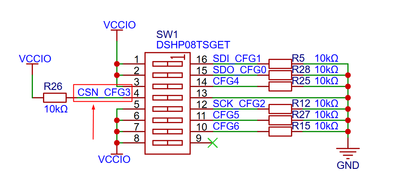
| DIP | Chip pin | Controls | Polarity |
|---|---|---|---|
| M1 | CFG1 | Microstep resolution (with M2) | Normal (down=0, up=1) |
| M2 | CFG0 | Normal (down=0, up=1) | |
| M3 | CFG4 | Run current IRUN (with M4, M5) | Normal (down=0, up=1) |
| M4 | CFG3 / CSN | Inverted (down=1, up=0) | |
| M5 | CFG2 | Normal (down=0, up=1) | |
| M6 | CFG5 | Chopper mode (SpreadCycle / StealthChop) | Normal (down=0, up=1) |
| M7 | CFG6 | Hold-current reduction | Normal (down=0, up=1) |
| NULL | — | Unused | — |
Microstep resolution — M1 / M2
| M1 | M2 | Microsteps |
|---|---|---|
| Down | Down | 8 |
| Down | Up | 16 |
| Up | Down | 32 |
| Up | Up | 64 |
Standalone mode only offers these four microstep settings. Fullstep or fine settings like 1/128 and 1/256 require SPI mode with the YAML microsteps: field.
Run current — M3 / M4 / M5 (with actual amps)
M3, M4 and M5 select one of eight current steps. The chip calls the setting IRUN, which is only a relative scale — so the table below converts each step into the actual motor current in amps for this board's 0.1Ω sense resistors. Remember M4 is inverted.
| M3 | M4 | M5 | IRUN | Current per coil (RMS) | Peak |
|---|---|---|---|---|---|
| Down | Up | Down | 16 | 1.22 A — lowest | 1.73 A |
| Down | Up | Up | 18 | 1.36 A | 1.93 A |
| Down | Down | Down | 20 | 1.51 A — factory default | 2.13 A |
| Down | Down | Up | 22 | 1.65 A | 2.34 A |
| Up | Up | Down | 24 | 1.80 A | 2.54 A |
| Up | Up | Up | 26 | 1.94 A | 2.74 A |
| Up | Down | Down | 28 | 2.08 A | 2.95 A |
| Up | Down | Up | 31 | 2.30 A — highest | 3.25 A |
run_amps can be set to any value. Always match the setting to your motor's rated phase current, never to the driver's maximum.
I_RMS = (GLOBALSCALER/256) × ((CS+1)/32) × (V_FS / R_SENSE) × 1/√2On this board
R_SENSE = 0.1Ω and V_FS = 0.325 V. In standalone mode nothing ever writes to the chip over SPI, so GLOBALSCALER stays at its reset default, which the datasheet defines as full scale (256) — making that term equal 1. CS is the IRUN value from M3/M4/M5. As a check, IRUN=31 gives 2.30 A RMS / 3.25 A peak, matching the datasheet's own sense-resistor table (2.3 A / 3.3 A at 0.1Ω).Tolerance: the chip's full-scale current tolerance is ±5%, before sense-resistor tolerance. Treat these as nominal values and verify on your own machine if the motor runs near its thermal limit.
If none of these eight steps matches your motor well, that is the main reason to use an SPI mode instead: its YAML run_amps: and hold_amps: fields set any current you want, in amps, and can be changed without touching the board.
Chopper mode — M6
| M6 | Result |
|---|---|
| Down (factory default) | SpreadCycle — more torque headroom, more audible |
| Up | StealthChop — the silent mode this driver is named for |
Hold-current reduction — M7
| M7 | Result |
|---|---|
| Down (factory default) | No reduction — hold current equals run current |
| Up | Hold current reduced to 50% of run current at standstill |
The as-shipped default (all eight switches down) is 8 microsteps, IRUN=20, SpreadCycle, no hold-current reduction — a safe low-current starting point, which is why every connection diagram in section 6 labels this the "DIP setting for min current."
Section 5Connect to a PiBot controller
All four current PiBot FluidNC controllers use the same I2S shift-register (I2SO.x) numbering for their first four external-driver connector positions, so this pin table applies whichever controller you use:
| Connector position | Disable (EN) | Direction | Step | SPI CS (SPI modes only) |
|---|---|---|---|---|
| 1st (often "X") | I2SO.0 | I2SO.1 | I2SO.2 | I2SO.3 |
| 2nd (often "Y") | I2SO.7 | I2SO.4 | I2SO.5 | I2SO.6 |
| 3rd (often "Y1"/"Z") | I2SO.8 | I2SO.9 | I2SO.10 | I2SO.11 |
| 4th (often "Z"/"A") | I2SO.15 | I2SO.12 | I2SO.13 | I2SO.14 |
5.1 V5.88 Ultra
V5.88 Ultra does have six on-board driver sockets, but the TMC5160 V5 does not use them. The board provides a separate set of EN / STP / DIR signal terminals dedicated to external drivers (item 13 on the V5.88 Pinout Reference), and unlike V4.96 Pro these need no slot jumper caps. Leave the on-board sockets empty — the single exception is SPI Independent mode, where the A4988 Socket-to-SPI Breakout Module plugs into one on-board socket purely to break out the SPI bus.
Normal (Standalone) mode
motor0:
  limit_neg_pin: NO_PIN
  limit_pos_pin: NO_PIN
  limit_all_pin: NO_PIN
  hard_limits: false
  pulloff_mm: 1.000
  standard_stepper:
    step_pin: I2SO.2        # 1st connector
    direction_pin: I2SO.1
    disable_pin: I2SO.0
SPI Daisy Chain mode
motor0: # 1st axis only sets cs_pin
  tmc_5160:
    r_sense_ohms: 0.1
    run_amps: 1.2
    hold_amps: 0.5
    microsteps: 16
    stallguard: 0
    toff_disable: 0
    toff_stealthchop: 5
    toff_coolstep: 3
    run_mode: CoolStep
    homing_mode: CoolStep
    use_enable: false
    cs_pin: i2so.3
    step_pin: I2SO.2
    direction_pin: I2SO.1
    disable_pin: I2SO.0
    spi_index: 1
    # 2nd/3rd/4th axis: spi_index 2/3/4, no cs_pin
SPI Independent mode
motor0: # repeat per axis with its own cs_pin
  tmc_5160:
    r_sense_ohms: 0.1
    run_amps: 1.2
    hold_amps: 0.5
    microsteps: 16
    stallguard: 0
    toff_disable: 0
    toff_stealthchop: 5
    toff_coolstep: 3
    run_mode: CoolStep
    homing_mode: CoolStep
    use_enable: false
    cs_pin: i2so.3          # .3 / .6 / .11 / .14 per axis
    step_pin: I2SO.2
    direction_pin: I2SO.1
    disable_pin: I2SO.0
    spi_index: -1           # -1 on every axis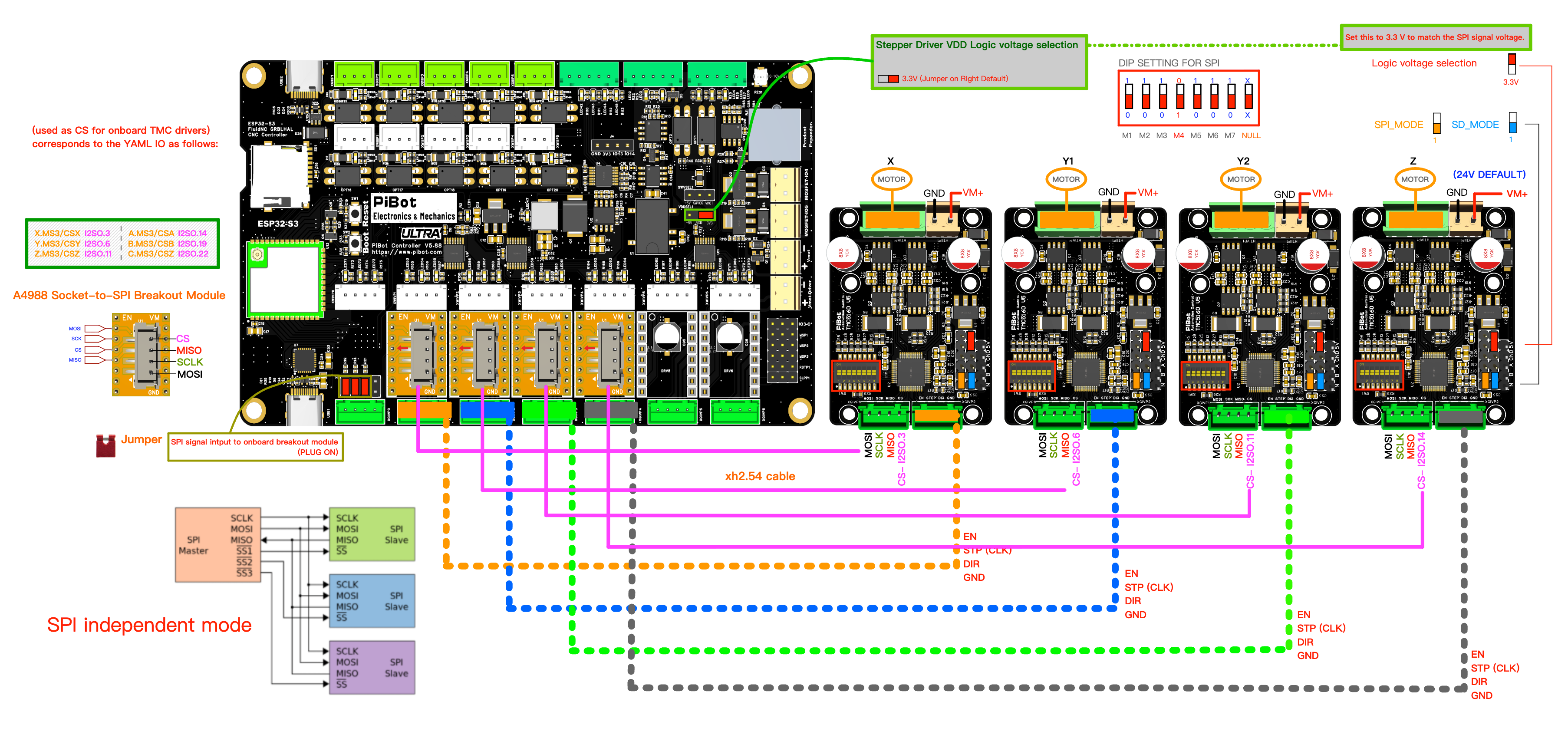
Verify SPI communication — the $MI command
After wiring either SPI mode, confirm the controller can actually talk to every driver before you let a motor move. In the FluidNC console (WebUI or FluidTerm) send:
$MIFluidNC reports the TMC drivers it found on the SPI bus, one line per driver. This applies to both SPI Daisy Chain and SPI Independent mode, on V5.88 Ultra and V4.96 Pro alike.
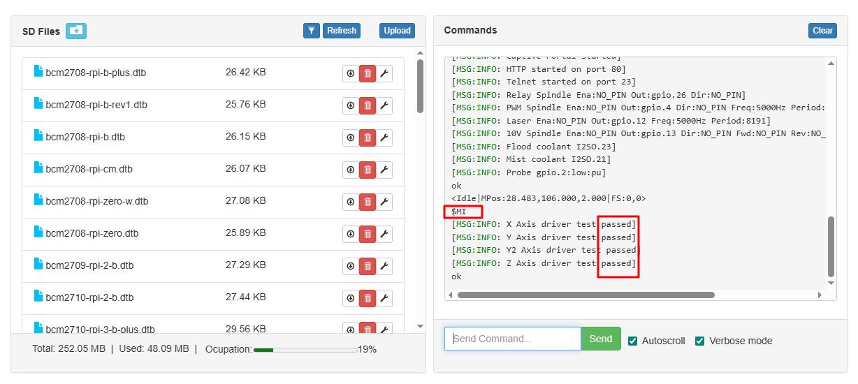
$MI output.Pass
Every driver you wired is listed, with sensible values. Only then proceed to a slow test jog.
Fail — what to check
- Logic voltage selection set to 3.3V on every driver board and on the mainboard's driver VDD jumper.
- SD_MODE = 1 and SPI_MODE = 1 on every driver board.
- Daisy chain:
cs_pinon the first axis only,spi_indexcounting 1, 2, 3, 4 along the chain. - Independent: each axis has its own
cs_pin, and everyspi_indexis-1. - MOSI / SCK / MISO and a common GND actually reach every board.
- Driver boards powered — 24V must be present, not just the logic supply.
5.2 V4.96 Pro
V4.96 Pro's six motor slots each support on-board StepStick, on-board SPI (TMC2130) or external drivers — the wiring below is for using the external connector output. Insert the slot jumper caps for the positions you're using externally, and remove any on-board StepStick/MS1/MS2/RST/SLP jumpers for those same slots.
Normal mode

standard_stepper YAML pattern as section 5.1.SPI Daisy Chain mode

tmc_5160 daisy-chain YAML pattern as section 5.1, CS on I2SO.3 only.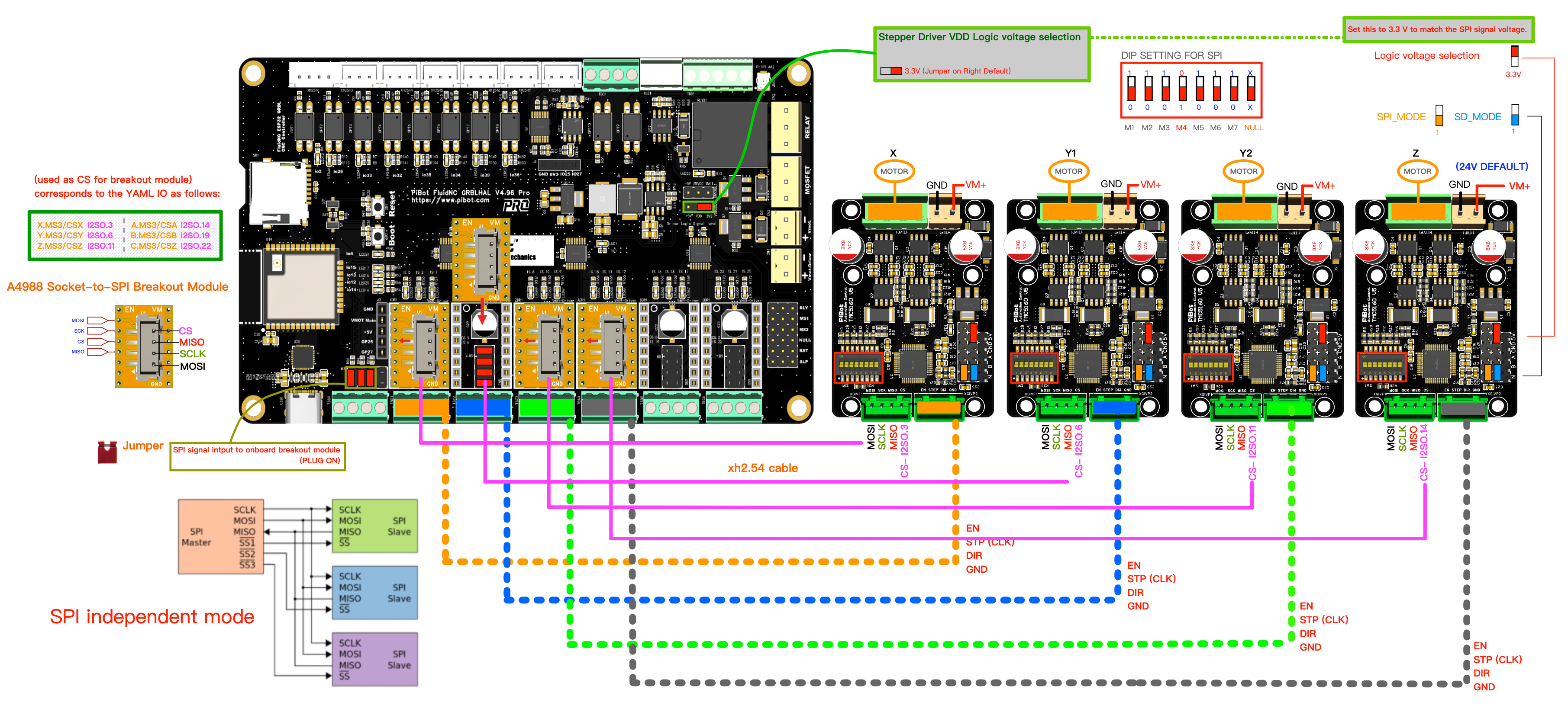
5.3 V5.77 Carrier

5.4 V4.7B

5.5 Mixing driver types
Not compatible
SPI mode is not compatible with Standalone mode on the same SPI/I2S bus. On-board SPI drivers (e.g. TMC2130) and external SPI TMC5160 V5 drivers cannot be mixed on a V4.96 Pro at the same time.
Compatible
On-board StepStick drivers can be mixed with TMC5160 V5 in Normal mode on different slots of the same controller, as long as each slot's jumpers match what that slot is actually driving.
Section 6Encoder and DIAG outputs
ABN encoder input
The TMC5160 supports feeding an ABN incremental encoder directly into the chip for closed-loop position/stall feedback, rather than returning encoder signals to the main controller. This only works in an SPI-controlled mode (not Standalone), and it reuses the CFG4/CFG5/CFG6 pins — see the warning in section 4. Configuration details are in the TMC5160 datasheet (linked in section 9).
DIAG0 / DIAG1 fault outputs
Broken out to a 3-pin header for wiring into a spare controller GPIO if you want hardware fault detection (overtemperature, short-circuit, StallGuard, etc.) instead of polling status over SPI. See the TMC5160 datasheet for the specific fault conditions each pin can report.
Section 7Main parameters
| Parameter | Value |
|---|---|
| Driver chip | TMC5160A-TA-T (Trinamic/Analog Devices) |
| Input voltage (this board) | 24V DC nominal, reverse-polarity and 33V surge-clamp protected. Not the wide range of the earlier V4 driver. |
| Sense resistor | 0.1Ω (100mΩ) per phase |
| Peak coil current | Up to 3.3A (same sense resistor as V4; consult the TMC5160 datasheet before changing sense resistors) |
| Logic / signal voltage | Selectable 3.3V or 5V (jumper) |
| Microstepping | 8/16/32/64 in Standalone mode; full SPI microstep range (down to 1/256) in SPI mode via YAML |
| Chopper modes | SpreadCycle, StealthChop (silent) |
| Feedback | ABN encoder input, DIAG0/DIAG1 fault outputs |
| Heatsink | Not required for normal use; not included |
| Compatible motors | NEMA17 / NEMA23 class 2-phase stepper motors |
| Dimensions | 56 × 42mm (identical footprint to V4) |
| Mounting holes | 4 × 3mm, 50.5 × 32mm spacing |
Section 8Dimensions

Section 9Documentation and downloads
Section 10Frequently asked questions
Does the motor spin as soon as I power it on?
No — EN is active-low and must be driven low by the controller (or tied low) before the driver will move the motor. Also confirm the driver and controller share a common GND.
Can I run this at 36V or higher?
Not officially. The board is specified for 24V input only. See the note in section 8 about the surge-clamp diode.
Do I need the A4988 Socket-to-SPI Breakout Module?
Only for SPI Independent mode on V5.88 Ultra or V4.96 Pro. Normal mode and SPI Daisy Chain mode don't need it.
Can I use this on V5.77 Carrier or V4.7B in SPI mode?
No. Neither board has an external SPI driver header, so there is no way to feed the SPI bus and chip-select lines to an external TMC5160. On those two boards this driver runs in Normal (step/dir) mode, and you set current and microstepping with the DIP switch.