PiBot V5.88 Ultra — Pin Definition Overview
FluidNC & grblHAL · 6 Dedicated + 1 Configurable Axis · ESP32-S3
The ports of FluidNC can all be freely defined and allocated through the YAML file, so there is no fixed PinMap.
Our current definition is based on the test YAML we use.
When applying it to your machine, you will need to define the pins yourself.
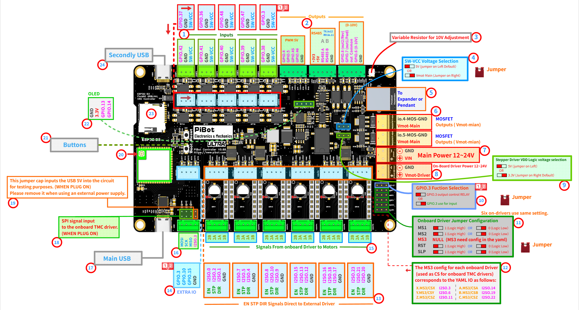
The circled numbers ①–㉔ on the diagram correspond to the sections below. Click the diagram to view it at full size.
Video Board Tour — Connectors, Outputs and Jumpers
Turney’s Builds provides a 6:24 close-up walkthrough of the V5.88 Ultra, including the dual USB-C ports, opto-isolated inputs, PWM and 0–10 V outputs, RS485, MOSFET channels, stepper-driver connections and configuration jumpers.
💡 Use the video as a visual orientation guide. FluidNC assignments can be changed in YAML; the numbered diagram, current PiBot test YAML and your machine-specific configuration remain the final references.
Quick Reference — UART Channels
| Channel | Physical Port | Pins (Test YAML) | Typical Use |
|---|---|---|---|
| UART0 | Main USB 17 | — | Firmware flashing, gcode sender |
| UART1 | RS485 terminal 2 | TX: GPIO.12 · RX: GPIO.11 | Modbus VFD |
| UART2 | RJ12 port 5 | TX: GPIO.0 · RX: GPIO.35 | Pendant / IO Expander |
| UART3 | Second USB 24 | USB-Host (usb_host) | USB pendant / HID device |
Key to the Circled Numbers
💡 Tip: If you find the following section challenging, don't worry. You can complete the checklist steps first and then come back — it will make much more sense.
Inputs
Outputs
Power
Drivers
Interface
1 Input Terminals Inputs
- 10 optocoupler-isolated input channels arranged in two rows along the top edge.
- Compatible input types: standard ON/OFF input, 5V signal switch, or industrial 12V/24V NPN switches. Every input already carries a 2.2 kΩ series resistor on the board, so no external resistor is needed, even at 24 V. PNP (sourcing) sensors are not compatible — see 4.1 Connect Limit Switches.
- SW-VCC selection: the optocoupler supply follows the SW-VCC jumper (see ④). Default 5V suits standard inputs; select Vmot-Main for industrial switches.
- NO/NC trigger polarity: configure in YAML by adding or removing the
:lowparameter. - GPIO.3 as input requires jumper selection first (see ⑩).
| Terminal | Test YAML Function | Terminal | Test YAML Function |
|---|---|---|---|
| GPIO.42 | X limit − | GPIO.37 | A limit − |
| GPIO.41 | X limit + | GPIO.36 | B limit − |
| GPIO.40 | Y limit − | GPIO.48 | C limit − |
| GPIO.39 | Y limit + | GPIO.47 | Probe |
| GPIO.38 | Z limit − | GPIO.3 | Toolsetter (jumper-selected, see ⑩) |
2 Output Groups Outputs
- PWM 5V — GPIO.4 GPIO.5 GPIO.45 GPIO.46: output 5V PWM signals or 5V switching signals for controlling spindles, lasers, servos, etc. Requires connection with any GND on the board to form a complete circuit.
- Test YAML: GPIO.45 = spindle PWM (tool 0), GPIO.46 = laser (tool 1), GPIO.4 = mist coolant (
M7), GPIO.5 = flood coolant (M8), andM9turns both coolant outputs off. - MOSFET linkage: GPIO.4 and GPIO.5 are interconnected with the onboard MOSFET channels (see ⑥).
- Test YAML: GPIO.45 = spindle PWM (tool 0), GPIO.46 = laser (tool 1), GPIO.4 = mist coolant (
- RS485 — TX: GPIO.12, RX: GPIO.11 (UART1): isolated RS485 interface for Modbus devices such as VFDs.
- A/B polarity: if A and B are reversed, simply swap them. Reversed connections will not cause device damage.
- Configuration reference: see the
ModbusVFDsection of the test YAML.
- 0-10V — GPIO.6 provides the 0-10V analog output for frequency converters (connect GPIO.6 output and GND, then configure to obtain the corresponding voltage).
- Optocoupler switches: GPIO.7 (Out1/Fwd) and GPIO.8 (Out2/Rev) with OUT-COMMON form switch pairs (both ends of optocouplers), usable as standard digital outputs to signal frequency converters.
- Start/stop function: for frequency converters requiring start/stop control, use these forward/reverse optocoupler outputs as the control signals.
3 Variable Resistor for 10V Adjustment Outputs
- Function: adjusts the maximum voltage of the 10V output.
- Calibration scenario: when issuing maximum output commands (e.g.,
M3 S24000), if the output voltage does not reach 10V. - Adjustment method: fine-tune this variable resistor until the output voltage reaches exactly 10V.
4 SW-VCC Voltage Selection Inputs
- Function: selects the voltage applied to the input-terminal optocoupler side.
- Options: 5V (jumper on left, default) OR Vmot-Main (jumper on right).
- Usage: keep 5V for standard switches and 5V sensors; select Vmot-Main for industrial 12V/24V switches. Your industrial switch voltage must match Vmot-Main.
- Voltage limit: the SW-VCC input circuit is designed for a maximum of 24V — never exceed 24V on Vmot-Main (see ⑦).
5 Expander / Pendant Port (RJ12) Interface
- Function: this port provides UART signals for pendant control or an IO expander module.
- Pins: UART2 — TX: GPIO.0, RX: GPIO.35 (test YAML baud: 1,000,000).
- Expander benefit: the expander provides additional I/O inputs and outputs for the mainboard.
- Compatibility: on V5.88 the pendant/expander port and the OLED (㉒) use independent pins — they can be used at the same time.
6 MOSFET Outputs Outputs
- Two channels:
io.4-MOS-GNDandio.5-MOS-GND(Vmot-Main). - Output capability: can output the same voltage as Vmot-Main or switch it off; used to drive inductive loads such as solenoid valves.
- Control principle: controlled via GPIO.4 or GPIO.5 by switching the GND connection to complete the circuit (low-side switching).
- Voltage note: Vmot-Main is the positive voltage, while the
io.4-MOS-GNDandio.5-MOS-GNDports serve as GND. - Flyback protection: onboard flyback diodes are provided for inductive loads.
⚠ Load limit: 500mA maximum per channel — the load current passes through the reverse-polarity protection circuit on the Vmot-Main path. For heavier loads, use these outputs to drive an external relay, SSR or suitable power driver instead. Overloading can burn the MOSFET.
⚠ Reverse connection of the load will damage the device! Always verify with a multimeter before use.
7 Main Power Input 12–24V Power
- Function: the system voltage input that provides stable power to logic, RS485, amplifiers, and other circuits.
- Reverse-polarity protection: built in — a reversed connection will not damage the board. Still, please verify polarity before powering up.
- Recommended voltage:
24Vinput is strongly recommended.
⚠ Never exceed 24V. Although the power regulator itself is rated to 30V, the onboard LM358 amplifier and the SW-VCC input circuit (2.2kΩ current-limit design) are limited to 24V. Exceeding 24V will damage components.
8 On-Board Driver Power 12–24V Power
- Function (Vmot-Driver): independent power input that supplies the six onboard stepper driver sockets only.
- Capacitor rating: our onboard electrolytic capacitors have a 50V withstand voltage rating.
- Driver requirements: some onboard driver modules contain capacitors with lower voltage tolerance, while others require
>12Vto generate proper signals. - Recommendation:
24Vis recommended.
⚠ This input has no reverse-polarity protection — a reversed connection may cause damage. Double-check polarity before powering up.
9 Stepper Driver VDD Logic Voltage Selection Drivers
- Function: this jumper selects the VDD logic voltage for stepper motor drivers (onboard or external).
- SPI drivers: since SPI signals are 3.3V, select
3.3Vwhen using SPI-type (TMC) stepper drivers. - 5V drivers: select
5Vfor external drivers requiring 5V logic signals. - Default setting:
3.3V(jumper on right). Choose according to your specific driver requirements.
10 GPIO.3 Function Selection Interface
- Function: this jumper selects the role of GPIO.3.
- Input mode: GPIO.3 is routed to the optocoupler input terminal (used as the toolsetter in the test YAML, see ①).
- Output mode: GPIO.3 is routed out as a signal output on the EXTRA IO header (see ⑭).
- Exclusive use: only one role at a time — set the jumper to match your YAML definition.
11 Onboard Driver Jumper Configuration Drivers
- Function: MS1 / MS2 / RST / SLP configuration switches for the onboard drivers — 1 (Logic High) OR 0 (Logic Low).
- MS3:
NULLon the switch panel — MS3 must be configured in the YAML via I2SO outputs (see ⑫). - Driver variations: some drivers support MS1/MS2/MS3, while others only support MS1/MS2. Some driver boards label these as
MS0/MS1/MS2— set according to actual pin functions. - Scope: the six onboard driver sockets share one setting — this configures all 6 drivers simultaneously.
⚠ When using onboard SPI-type (TMC) drivers, do NOT install these jumpers — these pins are used by the SPI interface. Only use them with standard (step/dir) onboard drivers.
12 MS3 / CS Mapping Drivers
- Function: MS3 pin configuration and corresponding I2SO numbers.
- Dual purpose: for SPI-type (TMC) drivers, the MS3 pin acts as the Chip Select (
CS) signal.
| Axis | MS3 / CS | YAML IO |
|---|---|---|
| X | X.MS3 / CSX | I2SO.3 |
| Y | Y.MS3 / CSY | I2SO.6 |
| Z | Z.MS3 / CSZ | I2SO.11 |
| A | A.MS3 / CSA | I2SO.14 |
| B | B.MS3 / CSB | I2SO.19 |
| C | C.MS3 / CSC | I2SO.22 |
13 EN / STP / DIR — Direct to External Drivers Drivers
- White terminals: output
EN/STP/DIRsignals directly to external stepper drivers. Simple — no jumper configuration needed. - The green terminals below them (⑮) carry the onboard driver outputs to the motors — the two terminal types serve different purposes.
| Axis | EN | STP | DIR | Axis | EN | STP | DIR |
|---|---|---|---|---|---|---|---|
| X | I2SO.0 | I2SO.2 | I2SO.1 | A | I2SO.15 | I2SO.13 | I2SO.12 |
| Y | I2SO.7 | I2SO.5 | I2SO.4 | B | I2SO.16 | I2SO.18 | I2SO.17 |
| Z | I2SO.8 | I2SO.10 | I2SO.9 | C | I2SO.23 | I2SO.21 | I2SO.20 |
14 EXTRA IO Outputs
- Header pins: GPIO.3 / GPIO.10 / GPIO.15 / GND.
- Test YAML: GPIO.10 = user output P0 (
M64 P0on /M65 P0off), GPIO.15 = user output P1 (M64 P1on /M65 P1off). GPIO.3 remains the toolsetter input and is tested in section 2.5. - 6+1 axis reuse: for a machine-specific seventh-axis configuration, set the GPIO.3 jumper to output mode, remove the toolsetter and user-output assignments from these three pins, and assign GPIO.3 / GPIO.10 / GPIO.15 as one Step / Dir / Enable group.
- Exclusive use: the three Extra I/O signals may form the additional motor group or perform their ordinary I/O roles, but cannot do both at the same time.
15 Onboard Driver → Motor Terminals Drivers
- Green terminals:
2B 2A 1A 1Bcoil pairs — the onboard driver outputs go to the motors through these terminals. - Direction reversal: swap one coil pair (e.g., 1A/1B) to reverse the motor direction, or invert the direction pin in the YAML.
16 SPI Signal Header Drivers
- Pins: MOSI / SCK / MISO / I2SO.3.
- Test YAML SPI bus: MOSI: GPIO.1, MISO: GPIO.2, SCK: GPIO.21.
- Purpose: SPI bus breakout for external SPI stepper drivers; I2SO.3 serves as the Chip Select (
CS) signal.
17 Main USB Interface
- Function (UART0): used for firmware flashing, configuration, and gcode sender connection.
18 SPI Input to Onboard TMC Drivers Drivers
- Function: routes the SPI bus to the onboard driver sockets (WHEN PLUG ON).
- Configuration: install this jumper block when using onboard SPI-type (TMC) drivers; remove it when SPI is not needed by the onboard drivers.
19 USB 5V Test Jumper Power
- Function: this jumper cap inputs the USB 5V into the circuit for testing purposes (WHEN PLUG ON).
- Important: please remove it when using an external power supply.
20 Antenna Connector Interface
- Important note: without an antenna connected, there will be no WiFi signal available.
21 Boot / Reset Buttons Interface
- Reset: restarts the controller.
- Boot: used for entering download mode during firmware flashing (hold Boot, tap Reset, then release Boot).
22 OLED Interface Interface
- Pins: GND / 3.3V / GPIO.13 (SCL) / GPIO.14 (SDA) — I2C address 0x3C, 128×64.
- Pinout caution: please note the positions of
VCCandGND, as some OLED modules have different pin arrangements. - Compatibility: on V5.88 the OLED can be used at the same time as the pendant/expander port (⑤).
23 TF Card Slot Interface
- Pins (test YAML): MISO: GPIO.2, MOSI: GPIO.1, SCK: GPIO.21, CS: GPIO.9.
- Compatibility warning: avoid using high-speed or high-capacity TF cards, as some may not be compatible with the ESP32 library.
24 Second USB (USB-Host) Interface
- Function (UART3): native USB port configured as USB-Host in the test YAML (
usb_host, baud 115200). - First-time setup: set
$USBCDC/Enable=Offbefore using this port for the first time. - Power note: this circuit can power the connected USB device in HID mode, but the controller cannot be powered through this USB port.