Frequently Asked Questions
FluidNC, Files and First Start
Can I use the supplied test YAML on my machine?
No. The supplied YAML deliberately enables many unrelated outputs and test functions so the board can be checked on a bench. Keep an untouched diagnostic copy, then create a machine-specific copy with the correct axes, steps/mm, direction, travel, homing, limits, spindle/laser and safety settings.
Which FluidNC firmware should I use?
Use the official FluidNC Web Installer or the package supplied for your controller. Select the target that matches the processor on your exact board: do not select an ESP32-S3 target for a classic ESP32-WROOM module, and do not flash firmware intended for another PiBot model.
Can the whole controller be tested from USB power only?
Usually no. USB may power the processor module, but the carrier board, 5 V buffers, optocouplers, motor-signal LEDs and power outputs require the board's specified main supply. Follow the power-on page for your model before testing I/O.
Why does FluidNC report a configuration error after I upload YAML?
Confirm that the uploaded file is plain text, that indentation uses spaces rather than tabs, and that the filename selected by $Config/Filename exactly matches the uploaded file. Read the first error in the boot log; later errors are often consequences of the first one.
Why is my TF/microSD card not detected?
This answer comes from the original V4.96 FAQ: avoid starting diagnosis with an excessively large or high-speed card because the ESP32 SD library and card compatibility vary. PiBot's earlier validation used a Class 4 TF card. Use a known-good FAT32 card, check the exact board's CS/MISO/MOSI/SCK mapping, insert it with power off, and read the first SD-related boot-log error.
Where are the original configuration examples?
Use the Documentation chapter for the exact controller. For example, the original V4.96 FAQ links to its XYYZAB configuration example. Do not use that file on V4.7B, V5.77 or V5.88.
Wi-Fi, WebUI and macOS
Why can I not find the FluidNC Wi-Fi network?
Wait at least 10 seconds after power-up, confirm the correct firmware was installed, and check the USB boot log. Disconnect optional pendants or expanders during diagnosis because a shared boot/UART signal held in the wrong state can prevent normal startup on some boards.
How do I open the factory Wi-Fi AP WebUI?
Join the controller's FluidNC access-point network, then open http://192.168.0.1 in Chrome or another modern browser. Do not add https:// for the controller's local AP address.
On a Mac, what should I do when captive.apple.com shows “You are disconnected”?
Click Cancel in the macOS captive-network window. Stay connected to the FluidNC Wi-Fi network, open Chrome manually, and enter http://192.168.0.1. The message only means the isolated controller network has no Internet access; it does not mean the FluidNC AP failed.
The WebUI disconnects while the controller restarts. Is that a fault?
No. A reboot, configuration reload or Wi-Fi change temporarily closes the browser connection. Wait for the controller to finish starting, reconnect to its Wi-Fi if needed, and reload the page.
Software and Laser Questions
Does LightBurn support FluidNC and grblHAL?
Yes. Current LightBurn documentation lists GRBL, FluidNC and grblHAL as supported GCode controller types. Select the appropriate device type and then verify laser mode, PWM pin, S-value range, dimensions, homing and interlocks on your actual machine.
Why do alternate raster engraving lines appear offset or doubled?
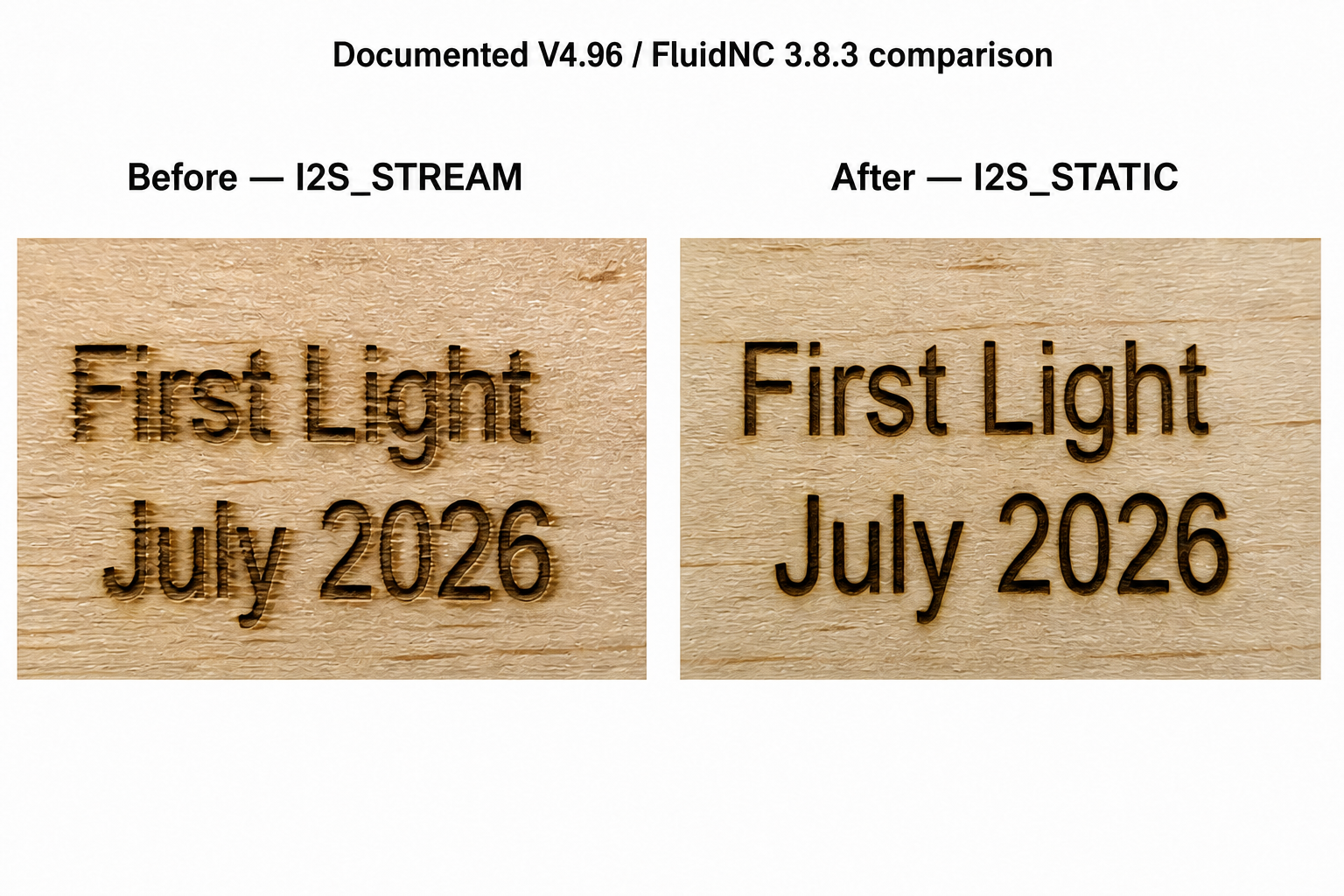
All boards First save the LightBurn file and record speed, acceleration, line interval/DPI and power. Engrave the same small text or rectangle once with bidirectional scanning and once with bidirectional scanning disabled. If the one-way result is clean while alternate two-way lines shift, continue below.
- Check X-axis belt tension, pulley set screws, carriage play, backlash and cable drag. Repeat at a lower speed and acceleration before applying compensation.
- Follow LightBurn's Scanning Offset Adjustment guide for a repeatable speed-dependent offset.
- I2SO FluidNC boards Back up the YAML. Change only
stepping.enginefromI2S_STREAMtoI2S_STATIC, restart and repeat the identical job. Do not also change steps/mm, speed, acceleration or pulse width. - If the comparison does not help, restore the backup and continue mechanical/speed diagnosis.
This is a documented comparison, not proof that every offset is a FluidNC fault or that every machine must use I2S_STATIC. See the original V4.96 case record and the FluidNC I2SO discussion.
Why do commands such as M7, M8 or M64 operate different terminals on different boards?
Those commands operate the pins assigned in the active YAML. PiBot test YAML files intentionally map them to convenient diagnostic outputs. Read the test page and YAML for your model instead of assuming that the command always belongs to a particular connector.
Can I use a closed-loop stepper driver?
From the original V4.96 FAQ: yes, when the driver accepts the controller's EN, DIR, CLK/STEP and GND signals. In that basic connection the controller sends motion signals but does not automatically receive the driver's encoder feedback. Use a separate compatible alarm/feedback input if the driver and machine design require it.
Pendant, I/O Expander and RJ12 RX/TX
All compatible boardsWhat can I do if an RJ12 pendant or I/O expander has no communication because RX and TX are reversed?
UART communication requires the TX signal at one end to reach RX at the other end. If power, ground and baud rate are correct but there is still no data, RX and TX may be reversed somewhere in the controller, adapter, expander, cable and pendant chain.
| Product or situation | Available correction | How to use it |
|---|---|---|
| PiBot Pendant V4.2 | Physical RX/TX jumper | Power off first, then move the onboard jumper to the required RX/TX direction. |
| PiBot I/O Expander V5 | Physical RX/TX jumper | Power off first, then use the expander's jumper to match the controller and downstream pendant. |
| PiBot RJ12 Adapter V4.2 | Physical RX/TX jumper | Power off first, then select the required RX/TX direction on the adapter. |
| Pendant running the latest ESP3D firmware | Software setting | Set communication mode to Serial, open Settings → Setting Editor, and change Swap RX TX. Test the opposite state if the current state has no communication. |
| Older pendant without an RX/TX jumper | Re-pin the approved signal cable | With all power disconnected, physically exchange only the identified RX and TX signal contacts in the detachable cable connector. |
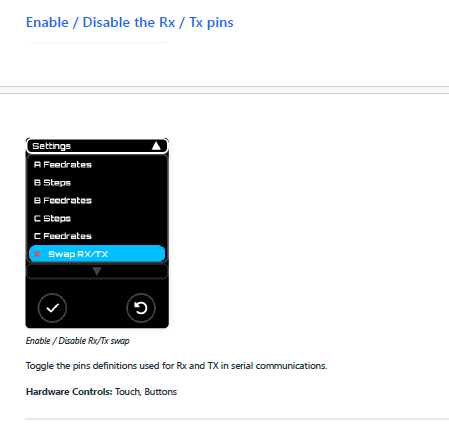
- Power off all devices and identify the exact revision printed on each board.
- Confirm the controller-specific UART mapping and make sure every device uses the same baud rate.
- For the latest ESP3D firmware, try Swap RX TX in software first.
- For Pendant V4.2, I/O Expander V5 or RJ12 Adapter V4.2, use one physical jumper as the correction point.
- For an older pendant without a jumper, exchange only the approved cable's RX/TX signal contacts.
- Power on and test after each single change. If communication starts, do not add another swap.
If the pendant works directly and the expander also works by itself, but they do not communicate when connected together, the complete chain is a strong candidate for an RX/TX direction mismatch. Use the Advanced Tests → Test RJ12 Port and Hardware Connection → Connect Pendant / Connect I/O Expander pages for the exact controller model.
Board-Specific Notes
All boardsMy PNP proximity sensor does not work. Why?
PiBot controller inputs source their own current. The board supplies it: the current flows out of the SW-VCC rail (or the internal 5 V rail on V4.7B), through an on-board resistor and the input optocoupler, and leaves through the Signal pin. An input therefore triggers only when your device pulls Signal down to GND.
A PNP (sourcing) sensor does the opposite — when it triggers it pushes V+ into the Signal pin. Because the optocoupler LED is already fed from the same rail, there is then no voltage across it and the input never changes state. Use an NPN (sinking) sensor instead; both NO and NC variants work, and you choose the polarity in YAML by adding or removing :low.
This applies to V4.7B, V4.96 Pro, V5.77 Carrier and V5.88 Ultra alike. On V4.96 and V5.88 a 30 V reverse-blocking Schottky diode protects each input, so a PNP sensor will not damage the board — it simply does nothing. V5.77 and V4.7B have no such diode, so do not leave a PNP sensor wired to them. On V4.7B never apply 12–24 V to a Signal pin at all: its inputs run from a fixed 5 V rail and there is no SW-VCC jumper. See the 4.1 Connect Limit Switches page of your board for wiring details.
V4.7BWhy must 12-24 V main power be connected during testing?
V4.7B is a carrier board. The ESP32 module can appear alive from USB while the carrier's 5 V supply, I2S buffers, output LEDs and power circuits are not operating. Connect correctly polarized 12-24 V main power before following the I/O checklist.
V4.7BWhy can OLED and the RJ12 pendant/expander not be used together?
Both functions share GPIO.25 and GPIO.27; V4.7B UART2 uses TX GPIO.27 and RX GPIO.25. The test YAML enables OLED and leaves UART2 commented. To test RJ12, disable the OLED section, enable the UART2 section, select the RJ12/expander hardware position, and restart.
V4.7BWhy are spindle Forward/Reverse unavailable during the RS485 test?
RS485 uses GPIO.15 for TX and GPIO.14 for direction. The same signals also feed the 0-10 V Forward/Reverse interface. The supplied test YAML reserves them for RS485 and leaves Forward/Reverse as NO_PIN; the analog 0-10 V signal on GPIO.13 can still be tested.
V4.7B / V5.77Where do StepStick drivers plug in?
They do not. These are carrier boards with Step/Dir/Enable outputs for external stepper drivers. V4.7B uses a classic 38-pin ESP32 DevKitC/WROOM-32 module; V5.77 uses its specified plug-in ESP32-S3 module.
V5.88 / V5.77What does “6+1” or “6+2” axes mean?
The board has six dedicated motor groups. Extra I/O signals may be configured as one additional motor group on V5.88 or two on V5.77, or used as ordinary I/O. The same signals cannot serve both purposes simultaneously.
V4.96 Original FAQ Items
V4.96Can a 24 V probe be used?
Yes, using an input that includes SW-VCC and setting that input supply to 24 V as shown in the V4.96 diagram overview. This answer is specific to V4.96's selectable SW-VCC input design; it must not be copied to V4.7B.
V4.96 / Expander V4What changed between I/O Expander V4.0 and V4.1?
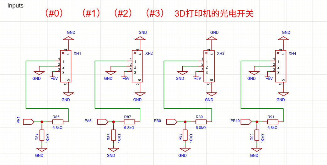
The original FAQ states that V4.1 added two voltage-divider resistors. Check the silkscreen on the back because the front silkscreen may be incorrect. When those ports are used as ordinary switches, the original instruction is to connect +5 V and signal; the divider presents about 3 V at the STM32 input, so configure high-level triggering.
V4.96Is there a customer video?
Yes. The original FAQ links to Customer Video 1 on YouTube.
V4.96What is the direct RJ12 UART2 mapping?
The current V4.96 direct-connection starting point is TX GPIO.27, RX GPIO.25, 1000000 8N1. For Pendant V4.2, I/O Expander V5, RJ12 Adapter V4.2, current ESP3D firmware and older-pendant correction methods, use the shared RJ12 RX/TX FAQ above.
V5.77 Original FAQ Items
V5.77Why does the board need a plug-in ESP32-S3 module?
V5.77 is a carrier board. The specified ESP32-S3 module provides the processor, Wi-Fi, USB and firmware storage. Seat it in the silkscreened orientation only while power is off.
V5.77Should the input jumper select GPIO 38 or GPIO 48?
The original V5.77 test YAML uses GPIO 38 for the Z limit. Choose GPIO 38 when the module's RGB LED occupies GPIO 48. If another module revision uses GPIO 38 for its LED, move the jumper to GPIO 48 and change the YAML pin.
V5.77Can 5 V and 24 V input sensors be mixed?
Not from the shared SW-VCC rail: its jumper selects one voltage for all ten headers. Use suitable external sensor power and safe common-ground/isolation practice for a mixed-voltage system.
V5.77Why do M64 P0/P1 not switch the MOSFET outputs?
In the original test YAML, M64/M65 P0-P5 control the six reserved I2SO outputs. The MOSFET channels use coolant commands: M7 for GPIO 4, M8 for GPIO 5 and M9 to turn both off.
V4.96 / V4.7B / V5.77How much load can each MOSFET output drive?
Each onboard MOSFET channel is rated at 1.5 A maximum and is intended for light loads. For a heavier load, use the channel to control an external relay or suitable power driver. Connecting a heavy load directly can burn the MOSFET.
V5.77Why does 0-10 V work but the VFD does not start?
The analog speed signal and run contacts are separate. Check GPIO 7 Forward / GPIO 8 Reverse with Out Common, the VFD terminal mode, analog input type, common, minimum frequency and interlocks. For RS485, check address, baud, model commands and A/B polarity.
V5.77The console repeats USB UNPLUGGED. Is that a fault?
Not when the native secondary USB channel is unused. The original FAQ instructs users to send $USBCDC/Enable=OFF when that channel is not used, and to re-enable/configure it before the optional USB-host test.
V5.88 Original FAQ Items
V5.88Does it have on-board stepper-driver sockets?
Yes, on all six dedicated axes. Each channel provides a Pololu-format on-board socket and an external 5 V Step/Dir/Enable output, with per-axis SPI chip select for supported SPI driver arrangements.
V5.88Which jumpers must be checked before first power-on?
The original FAQ lists SW-VCC Voltage Selection, Stepper Driver VDD Logic Voltage Selection and GPIO 3 Function Selection. Follow the V5.88 2.2 Check Jumpers and Power On page and re-check them whenever the driver type or Extra I/O use changes.
V5.88Could a driver module be inserted backwards?
Yes. Match its orientation to the socket silkscreen before power-on. Never hot-plug drivers, motors, OLED or pendant equipment.
V5.88How much load can each MOSFET output drive?
Each io.4/io.5 channel is rated at 500 mA maximum. Use an external relay or suitable power driver for heavier loads; connecting a heavy load directly can burn the MOSFET.
V5.88What are the factory FluidNC AP details?
The original FAQ lists SSID fluidnc, password 12345678 and WebUI http://192.168.0.1. Wait about ten seconds after boot before searching for the network.
V5.88The console repeats USB UNPLUGGED. Is that a fault?
No when using the CP2102 USB path while the ESP32-S3 native USB channel is unused. The original FAQ recommends $USBCDC/Enable=OFF if the native channel is not required.